medical stent
A medical and coil technology, applied in the field of medical stents, can solve problems such as difficult to identify wing parts, and can hardly expect X-ray visibility, etc., and achieve the effect of improving contrast
- Summary
- Abstract
- Description
- Claims
- Application Information
AI Technical Summary
Problems solved by technology
Method used
Image
Examples
no. 1 Embodiment approach )
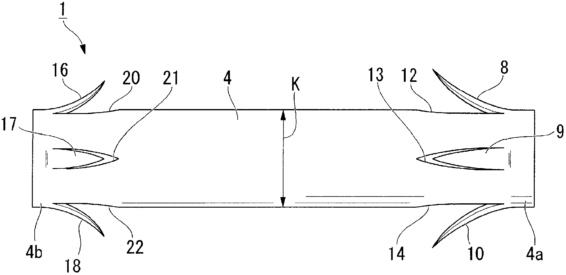
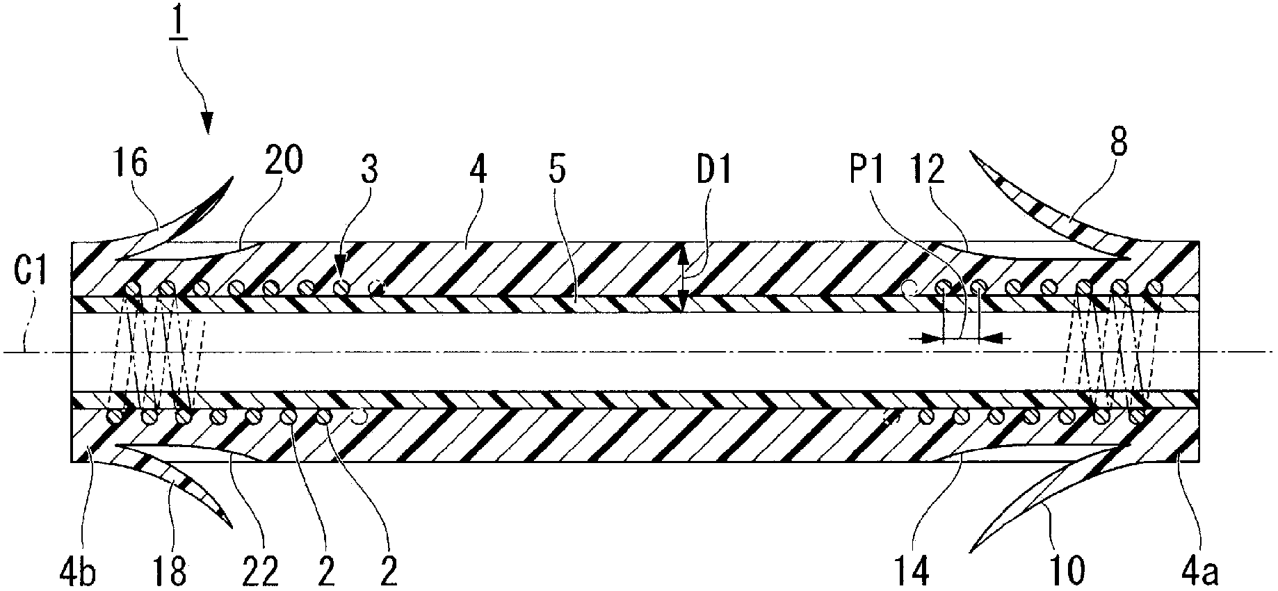
[0058] Below, refer to Figure 1 to Figure 9 A first embodiment of the stent of the present invention will be described. The stent of this embodiment is indwelled in the bile duct of a living body by using a stent delivery catheter or the like used endoscopically. In addition, in all the following drawings, the thickness and dimensional ratio of each component are suitably different from the actual size in order to make the drawings easier to see.
[0059] Such as figure 1 and figure 2 As shown, the stent 1 of the present embodiment has a coil 3 formed by winding a wire 2 around an axis C1, an outer layer 4 formed in a substantially tubular shape and provided coaxially with the coil 3 on the outer peripheral side of the coil 3 , and a substantially tubular and formed outer layer 4 . The inner layer 5 is provided coaxially with the coil 3 on the inner peripheral side of the coil 3 .
[0060] The wire 2 is made of metal such as tungsten steel, stainless steel, which is an X...
no. 2 Embodiment approach )
[0125] Next, a second embodiment of the present invention will be described. In this embodiment, the same reference numerals are assigned to the same parts as those in the first embodiment, and descriptions thereof will be omitted, and only differences will be described.
[0126] Such as Figure 10As shown, the stent 31 of this embodiment has a coil 33 instead of the coil 3 of the stent 1 of the first embodiment, and the coil 33 includes a predetermined position on the axis C1 where the coil 3 is wound around the axis C1 in a substantially tight roll. Marker coil part 32 made of the wire material 2 of the first embodiment, and normal winding coil parts 34 and 35 wound at the same pitch P1 as the wire material 2 of the coil 3 of the first embodiment.
[0127] In addition, "substantially densely coiled" as used herein means that the wire rod is wound at a constant pitch that is greater than 1 time and 7 times or less the outer diameter of the wire rod. For example, in this emb...
no. 3 Embodiment approach )
[0153] Next, a third embodiment of the present invention will be described, but the same parts as those in the first and second embodiments will be assigned the same reference numerals and their description will be omitted, and only the different points will be described.
[0154] Such as Figure 14 As shown, the stent 51 of the present embodiment has a coil 53 instead of the coil 33 of the stent 41 of the modified example of the second embodiment.
[0155] The coil 53 includes a common winding coil portion 35, marking coil portions 42, 43 respectively arranged at both ends of the coil 53, a sparse winding coil portion 54 disposed between the ordinary winding coil portion 35 and the marking coil portion 42, and a coil portion 54 located between the normal winding coil portion 35 and the marking coil portion 42. The open coil portion 55 between the normal wound coil portion 35 and the marker coil portion 43 .
[0156] In this embodiment, it is preferable that the pitch P1 of t...
PUM
 Abstract
Description
Claims
Application Information
 - R&D
- Intellectual Property
- Life Sciences
- Materials
- Tech Scout
- Unparalleled Data Quality
- Higher Quality Content
- 60% Fewer Hallucinations
Browse by: Latest US Patents, China's latest patents, Technical Efficacy Thesaurus, Application Domain, Technology Topic, Popular Technical Reports.
© 2025 PatSnap. All rights reserved.Legal|Privacy policy|Modern Slavery Act Transparency Statement|Sitemap|About US| Contact US: help@patsnap.com


