Current sensor fault reconstruction method and device

A Current Sensor, Fault Reconstruction Technology

Active Publication Date: 2016-06-01
HUNAN UNIV OF TECH
View PDF5 Cites 2 Cited by
  • Summary
  • Abstract
  • Description
  • Claims
  • Application Information

AI Technical Summary

Problems solved by technology

[0005] The present invention provides a current sensor fault reconstruction method and device to solve the technical problem that the current sensor fault cannot be reconfigured in the permanent magnet synchronous motor control system in the prior art

Method used


Image

  • Current sensor fault reconstruction method and device
  • Current sensor fault reconstruction method and device
  • Current sensor fault reconstruction method and device

Examples


Embodiment 1

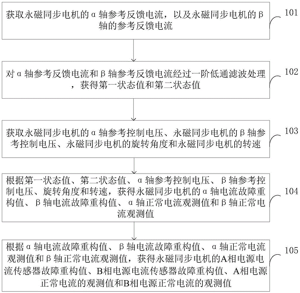
[0057] The executive subject of the current sensor fault reconstruction method in this embodiment is the current sensor fault reconstruction device, figure 1 It is a schematic flow chart of a current sensor fault reconstruction method according to Embodiment 1 of the present invention, as figure 1 As shown, this embodiment provides a current sensor fault reconstruction method, the method is based on a permanent magnet synchronous motor control system, including:

[0058] Step 101, obtain the α-axis reference feedback current i of the permanent magnet synchronous motor α , and the reference feedback current i of the β-axis of the permanent magnet synchronous motor β .

[0059] Step 102, refer to the feedback current i for the α-axis α and the β-axis refer to the feedback current i β After a first-order low-pass filtering process, the first state value z is obtained 1 and the second state value z 2 .

[0060] Step 103, obtain the α-axis reference control voltage u of the ...

Embodiment 2

[0067] This embodiment is a supplementary description based on the above embodiments.

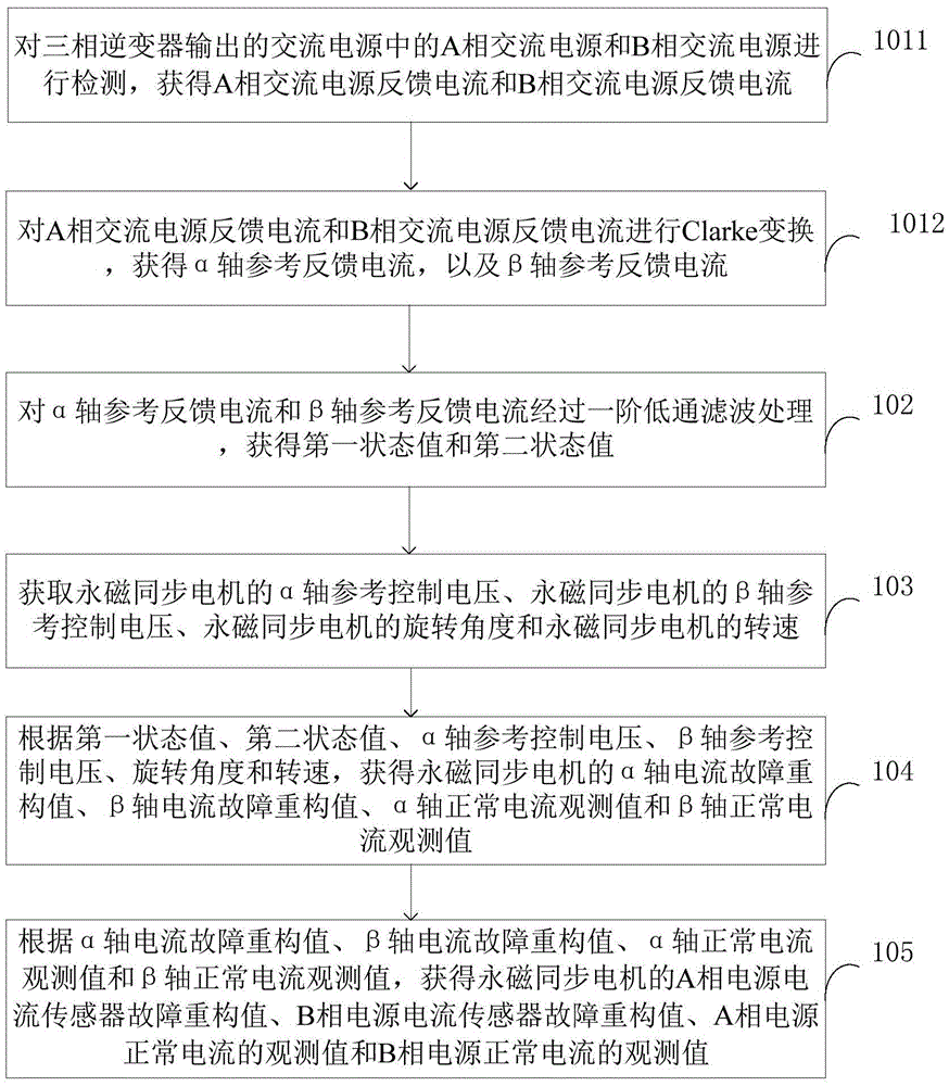
[0068] figure 2 It is a schematic flow chart of a current sensor fault reconstruction method according to Embodiment 2 of the present invention, as figure 2 As shown, this embodiment provides a current sensor fault reconstruction method, the method is based on a permanent magnet synchronous motor control system, including:

[0069] Step 101, obtain the α-axis reference feedback current i of the permanent magnet synchronous motor α , and the reference feedback current i of the β-axis of the permanent magnet synchronous motor β .

[0070] Further, step 101 specifically includes:

[0071] Step 1011: Perform signal detection on the A-phase AC power supply and the B-phase AC power supply in the AC power supply output by the three-phase inverter, and obtain the feedback current i of the A-phase AC power supply A and B-phase AC power feedback current i B .

[0072] Specifically, signal de...

Embodiment 3

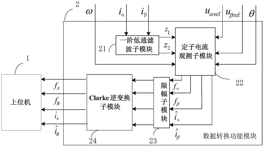
[0098] The current sensor fault reconfiguration device of this embodiment is used to implement the above current sensor fault reconfiguration method. image 3 It is a schematic structural diagram of a current sensor fault reconfiguration device according to Embodiment 3 of the present invention, as image 3 As shown, this embodiment provides a current sensor fault reconstruction device, the device is based on the permanent magnet synchronous motor control system, including: a data conversion function module 2, the data conversion function module 2 includes a first-order low-pass filter sub-module 21. The stator current observation sub-module 22, the limiting sub-module 23 and the Clarke inverse transformation sub-module 24; the stator current observation sub-module 22 is respectively connected with the first-order low-pass filter sub-module 21 and the limiting sub-module 23, and the limiting sub-module 23 is also connected with the Clarke inverse transform sub-module 24.

[0...


PUM


Abstract

The invention provides a current sensor fault reconstruction method and device. The method comprises the following steps: obtaining an alpha-axis reference feedback current i<alpha> and a beta-axis reference feedback current i<beta>; obtaining a first state value z<1> and a second state value z<2> through first-order low-pass filter processing on the i<alpha> and the i<beta>; obtaining an alpha-axis current fault reconstruction value f<alpha>, a beta-axis current fault reconstruction value f<beta>, an alpha-axis normal current observation value as shown in the specification and a beta-axis normal current observation value as shown in the specification according to the z<1>, the z<2>, an alpha-axis reference control voltage u<alpharef>, a beta-axis reference control voltage u<betaref>, a rotating angle theta and a rotating speed omega; obtaining an A-phase power supply current sensor fault reconstruction value f, a B-phase power supply current sensor fault reconstruction value f, an A-phase power supply normal current observation value as shown in the specification and a B-phase power supply normal current observation value as shown in the specification according to the f, the f, the alpha-axis normal current observation value as shown in the specification and the beta-axis normal current observation value as shown in the specification. The method not only can judge the position of the fault, but also can effectively and accurately obtain a fault signal mixed in the normal current, so that relatively accurate fault diagnosis information is obtained; and the current sensor fault reconstruction function is achieved.

Description

technical field [0001] The invention relates to the technical field of permanent magnet synchronous motors, in particular to a current sensor fault reconstruction method and device. Background technique [0002] The permanent magnet synchronous motor control system has the advantages of high efficiency, high control precision, stable torque and low vibration and noise. It has good application prospects in many fields and is widely used in electric vehicles, industrial sewing machines, air conditioners, elevators and higher precision Applications such as CNC machine tools and robots. [0003] In order to ensure the safety and reliability of the permanent magnet synchronous motor, it is necessary to monitor its operating status in real time during the working process of the permanent magnet synchronous motor, and to be able to judge in time when the components of the permanent magnet synchronous motor control system fail If the key components such as the power module and curr...

Claims


Application Information

Patent Timeline
IPC IPC(8): H02P21/13H02P21/22H02P27/06
CPCH02P21/13H02P27/06
Inventor 张昌凡廖慧君何静廖无限李祥飞吴公平孙健林真珍
Owner HUNAN UNIV OF TECH
Why Eureka
Try Eureka