
Fault locating apparatus of non-contact electromagnetic induction of AT power traction system and fault locating method thereof

A technology of electromagnetic induction and fault location, applied in fault location, information technology support system, etc., can solve difficult to achieve, frequency-dependent effect of traveling wave signal parameters, difficult to extract and process traveling wave signal, and inaccurate time of different monitoring points. Synchronization and other problems to achieve the effect of improving efficiency, troubleshooting and restoring power supply, saving manpower and material resources

Active Publication Date: 2013-08-14
SOUTHWEST JIAOTONG UNIV
View PDF5 Cites 0 Cited by
  • Summary
  • Abstract
  • Description
  • Claims
  • Application Information

AI Technical Summary

Problems solved by technology

In recent years, traveling wave ranging technology has been applied to fault location of traction power supply system, but the uncertainty of traveling wave signal and the frequency variation effect of parameters often make the extraction and processing of traveling wave signal very difficult; Due to the inability of accurate synchronization and the inability of the existing communication network to transmit fault data in batches, the traveling wave ranging and positioning method is feasible in principle, but it is difficult to achieve in practical applications.

Method used


Image

  • Fault locating apparatus of non-contact electromagnetic induction of AT power traction system and fault locating method thereof
  • Fault locating apparatus of non-contact electromagnetic induction of AT power traction system and fault locating method thereof
  • Fault locating apparatus of non-contact electromagnetic induction of AT power traction system and fault locating method thereof

Examples


Embodiment

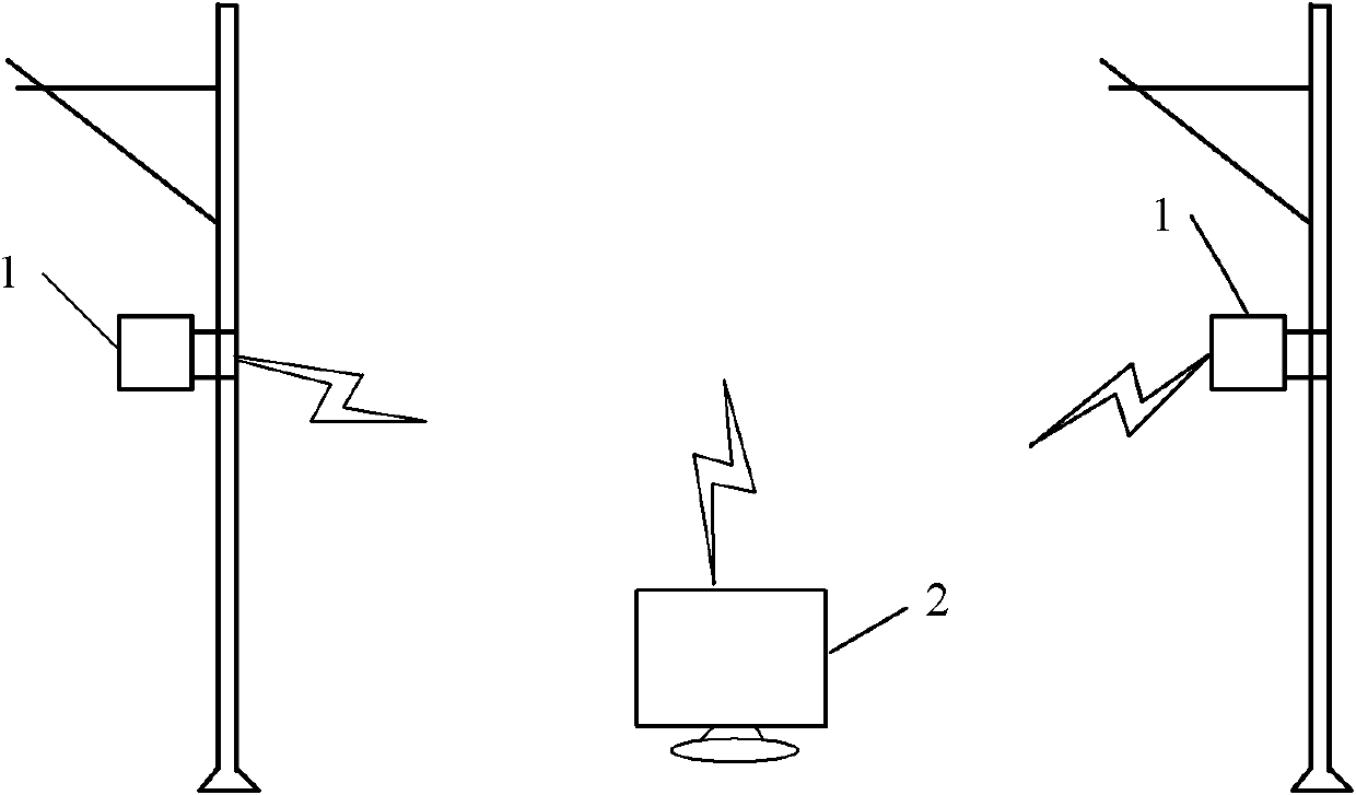
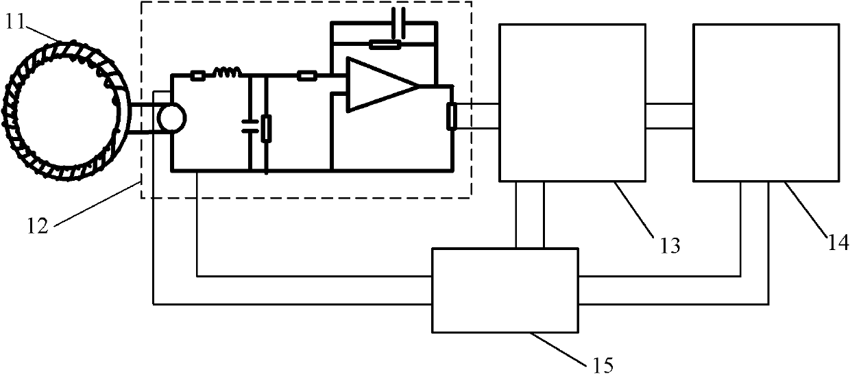
[0023] figure 1 , figure 2 As shown, a specific embodiment of the present invention is a non-contact electromagnetic induction fault location device for an AT power supply traction network, which consists of:

[0024] An electromagnetic induction fault locator 1 is installed on the traction network pole tower of the AT power supply mode, and a remote terminal computer 2 with a GSM signal receiving module is installed at the traction substation; the electromagnetic induction fault locator is composed of an electromagnetic induction coil 11, a voltage amplification circuit 12. The single-chip microcomputer 13 and the GSM signal transmitting module 14 are sequentially connected to form, and the voltage amplifying circuit 12 , the single-chip microcomputer 13 and the GSM signal transmitting module 14 share a power supply 15 .

[0025] image 3 It is shown that the power source 15 of this example is a solar power source composed of a solar panel 15A, a solar charge controller 15...


PUM


Abstract

The invention discloses a method for performing fault location to an AT power traction system by using a fault locating apparatus of non-contact electromagnetic induction. The fault locating apparatus of non-contact electromagnetic induction comprises: an electromagnetic induction fault locater (1), which is installed on a traction system tower of an AT power mode; and a remote terminal computer (2), which carries a GSM signal receiving module and is installed at a traction substation. The electromagnetic induction fault locater is composed of an electromagnetic induction coil (11), a voltage amplifier circuit (12), a signal chip microcomputer (13), and a GSM signal transmitter module (14), wherein the electromagnetic induction coil, the voltage amplifier circuit, the signal chip microcomputer, and the GSM signal transmitter module are connected successively. Besides, power source (15) is shared by the voltage amplifier circuit (12), the signal chip microcomputer (13), and the GSM signal transmitter module (14). According to the invention, the method has advantages of low cost of installation operation, high precision of location, and fast locating speed, so that safety, reliability, and high efficiency of the operation of a train can be better ensured.

Description

technical field [0001] The invention relates to a fault location method for a traction network of a traction power supply system, in particular to a fault location method for a traction network by non-contact electromagnetic induction measurement. Background technique [0002] With the rapid development of high-speed and heavy-duty railways in my country, the AT power supply method is widely favored by high-speed railways at home and abroad due to its advantages such as long power supply distance, low voltage loss of traction network and strong anti-interference ability. On the basis of the double-line AT power supply mode, the uplink and downlink traction networks share a circuit breaker at the outlet of the traction substation, and the contact lines, rails and positive feeders of the uplink and downlink traction networks pass through the cross-connection line object in all AT stations Parallel connection is the full parallel AT power supply mode. Compared with the AT powe...

Claims


Application Information

Patent Timeline
Patent Type & Authority Patents(China)
IPC IPC(8): G01R31/08
CPCY04S10/52
Inventor 何正友林圣钱澄浩胡海涛吴双
Owner SOUTHWEST JIAOTONG UNIV
Learn More