Bin discharge mechanism of circular bin

A silo, circular technology, applied in the field of couplings, can solve the problems of inability to withstand reverse axial force, time-consuming and labor-intensive, etc., and achieve the effects of low processing cost, convenient manufacturing, and improved bearing capacity.

Active Publication Date: 2016-06-08
MYANDE GRP CO LTD
View PDF7 Cites 8 Cited by
  • Summary
  • Abstract
  • Description
  • Claims
  • Application Information

AI Technical Summary

Problems solved by technology

[0004] Since the coupling of the silo machine in the prior art cannot withstand the reverse axial force generated by the reversal, the silo roof can only be lifted, and it takes half a month to a month to remove the silo. The material is cleaned up, and then the auger shaft can be restarted, which is time-consuming and laborious

Method used


Image

  • Bin discharge mechanism of circular bin
  • Bin discharge mechanism of circular bin
  • Bin discharge mechanism of circular bin

Examples


Embodiment Construction

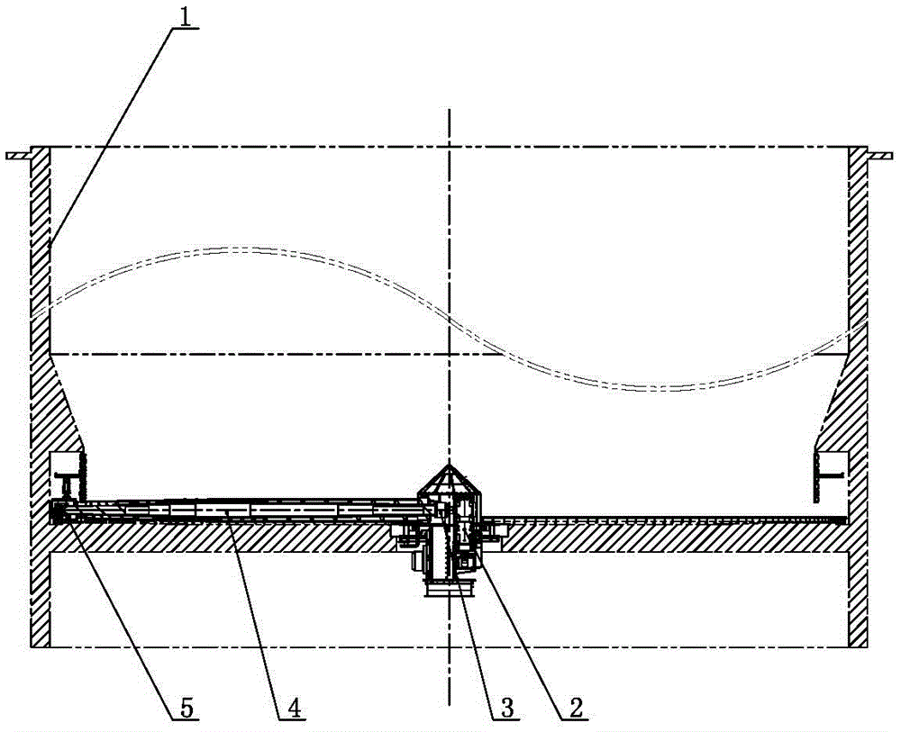
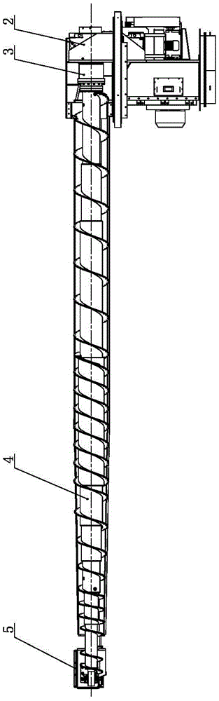
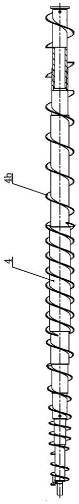
[0031] Such as Figure 1 to Figure 6 As shown, the discharge mechanism of the circular feed bin of the present invention comprises a main reducer 2, a coupling 3, a discharge auger 4 and a tail mechanism 5, the main reducer 2 is located at the center of the feed bin 1, and the main reducer 2 The output shaft of the output shaft is connected with the inner end of the auger shaft of the discharge auger 4 through the coupling 3, the outer end of the auger shaft is connected with the tail mechanism 5, and the parts other than the two ends of the auger shaft are formed by a plurality of hollow long The shafts 4a are nested in sequence and welded to each other, and the closer to the middle part of the auger shaft, the more nesting layers, so that the auger shaft is a stepped shaft with the largest diameter in the middle section, and the outer circumference of the auger shaft is wound with helical blades 4b in the axial direction , the pitch of the helical blade 4b on each step axis ...


PUM


Abstract

The invention relates to a bin discharge mechanism of a circular bin. The bin discharge mechanism comprises a main speed reducer, a coupling, a discharge auger and a tail mechanism; the main speed reducer is positioned in center of the bin; an output shaft of the main speed reducer is connected with an auger shaft of the discharge auger through the coupling; an outer end of the auger shaft is connected with the tail mechanism; the part, beside two ends, of the auger shaft is formed by embedding and welding multiple hollow long shafts in sequence; the number of embedded layers near the middle part of the auger shaft is bigger; spiral blades are axially wound at the outer periphery of the auger shaft, and are uniform in pitches on each section of step shaft; and the volumes in the pitches of the spiral blades are gradually increased from tail ends to center ends. Blades for shearing materials are respectively mounted on the outer edges of all the spiral blades. The output shaft of the main speed reducer is supported on wall boards on two sides of the main speed reducer through double rows of radial spherical roller bearings; and a two-way thrust ball bearing is mounted at one end, far from the discharge auger, of the output shaft of the main speed reducer. The bin discharge mechanism can bear higher radial force and two-way axial force, and is low in failure rate.

Description

technical field [0001] The invention relates to a shaft coupling, in particular to a bin discharge mechanism for a circular feed bin, and belongs to the technical field of bin discharge machines. Background technique [0002] Grain, soybean meal and other materials are usually placed in silos for long-term storage, and the bottom of the silo is equipped with a discharge machine for outputting materials. The discharge port of the silo is located at the bottom center of the silo. The main shaft system of the discharge machine includes the main reducer, coupling, auger shaft and tail end bearing. The main reducer is located on the axis of the silo, and the output of the main reducer is The shaft is connected with the driving end of the auger shaft through a coupling, and the outer end of the auger shaft is supported on a circular guide rail through a tail end bearing. When discharging, the main reducer drives the auger shaft to rotate through the coupling, and the auger shaft ...

Claims


Application Information

Patent Timeline
Patent Type & Authority Applications(China)
IPC IPC(8): B65G65/46B65G33/32B65G33/26B65G69/14
CPCB65G33/26B65G33/32B65G65/46B65G69/14
Inventor 徐静李旭东陈婷吕岩峰方世文
Owner MYANDE GRP CO LTD
Why Eureka
Try Eureka