Wire end fixing method and device of wire winding spool

A fixing method and I-shaped wheel technology are applied in the field of metal wire deep processing to achieve the effect of improving labor efficiency, reducing labor intensity and ingenious principle.

Inactive Publication Date: 2016-06-08
JIANGNAN UNIV
View PDF10 Cites 4 Cited by
  • Summary
  • Abstract
  • Description
  • Claims
  • Application Information

AI Technical Summary

Problems solved by technology

[0005] The present invention aims at the cumbersome operation of manually fixing the thread ends in the winding and winding process of the existing metal wire products, and provides a method and device for fixing the thread ends of the winding I-shaped wheel, which effectively realizes the processing process of the thread ends when the I-shaped wheel winds and takes up the wire Automation, improve production efficiency, reduce labor costs and production costs

Method used


Image

  • Wire end fixing method and device of wire winding spool
  • Wire end fixing method and device of wire winding spool
  • Wire end fixing method and device of wire winding spool

Examples


Embodiment Construction

[0023] The specific implementation manner of the present invention will be described below in conjunction with the accompanying drawings.

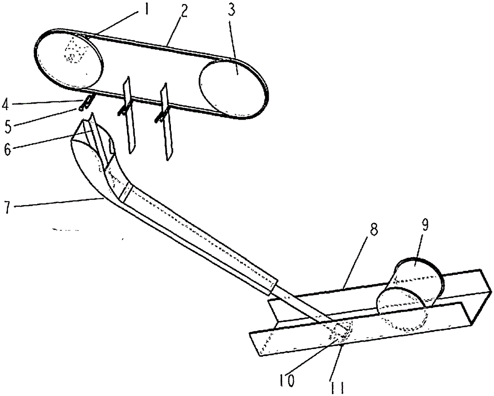
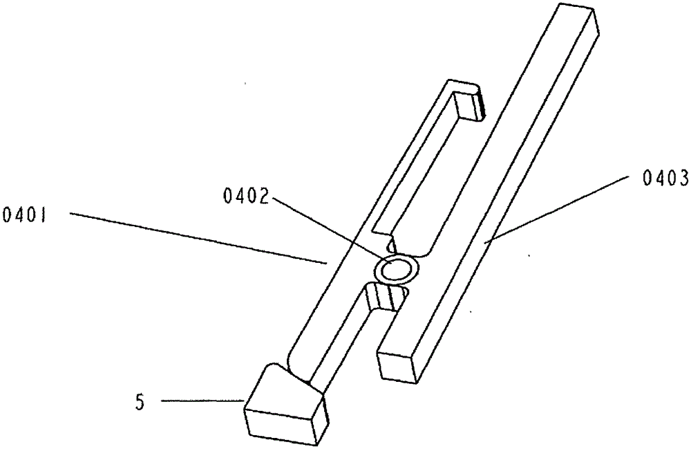
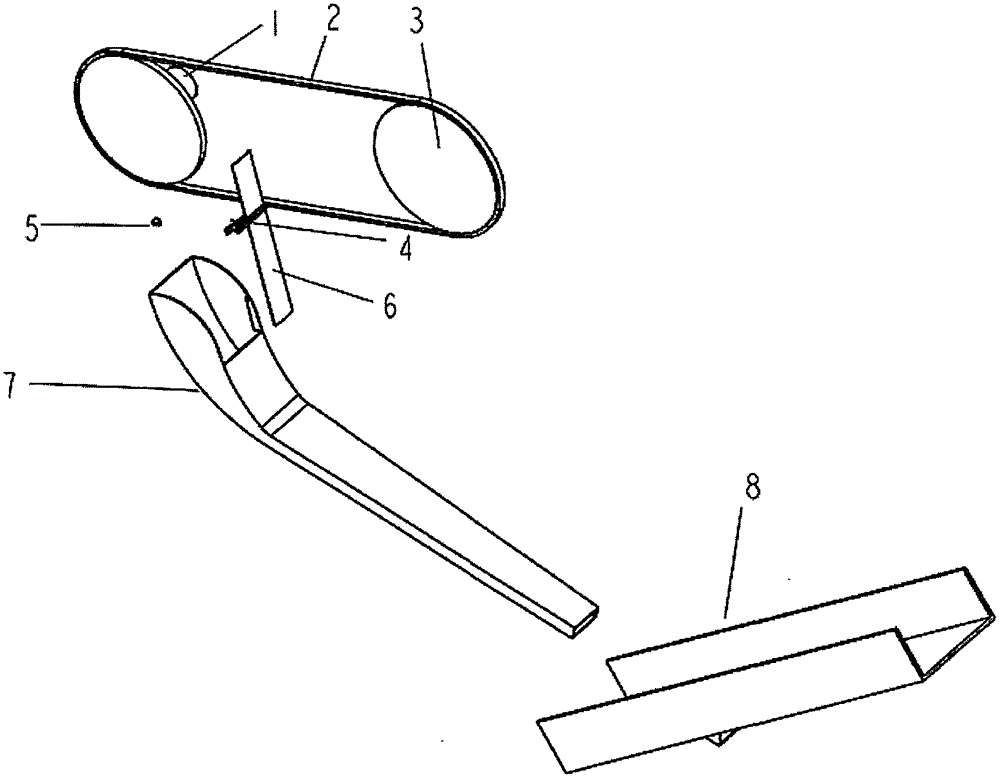
[0024] As shown in the accompanying drawings, the present invention includes two sprockets 3 driven by a stepping motor 1, a transmission chain 2, and several regularly arranged spring clips 4 fixed to one side of the transmission chain 2 with bolts, clamped in the spring clip 4 The self-rolling steel sheet 6 between the sheets is fixedly installed on the spring clip stopper 5 on the frame, and the moving spring clip 4 can touch the spring clip stopper 5; the fixed steel sheet slides under the spring clip stopper 5 Road 7, the I-shaped wheel slideway 8 with adjustable inclination angle and the center alignment device of the steel sheet slideway 7, said I-shaped wheel slideway 8 has a long hole, and a steel sheet blocking block 10 is installed below the long hole, and the steel sheet Shock-absorbing rubber pad 11 is arranged before the bloc...


PUM


Abstract

The invention relates to a wire end fixing method and a device of a wire winding spool. The device comprises a chain transmission mechanism driven by a stepper motor, multiple spring clips fixed on one side of a conveying chain and regularly arranged, spring clip stoppers and steel piece slide ways fixedly mounted, inclined angle-adjustable spool slide ways and the like. Self-wound steel piece with a certain specification are clamped on the spring clips; and when a wire winding machine begins to wind wires, chain wheels rotate to drive the conveying chain and the spring clips to move, so that movable clamping pieces of the spring clips touch the spring clip stoppers to be opened, then, the self-wound steel pieces downwards slide to an appointed position for fixation along the steel piece slide ways to finish rolling down of the wire winding spool along the spool slide ways, a certain shock is given to the self-wound steel pieces to generate self winding to wrap wire ends on the spool, and coil wire heads are fixed. The device has the characteristics of simple structure, easiness in control and excellent wire end fixing effect.

Description

Technical field [0001] The invention belongs to the technical field of metal wire deep processing, and relates to an auxiliary device of an I-shaped wheel take-up machine, in particular to a method and a device for fixing the end of an I-shaped wheel winding wire. [0002] The I-shaped wheel take-up machine is a continuous production equipment commonly used in the metal wire products industry. The I-shaped wheel is used to wind and take up the metal wire products to facilitate the use and transportation of finished or semi-finished wire products. The products are neat and beautiful. The device of the present invention can automatically fix the cut wire end on the I-shaped wheel during the winding and taking-up process of the metal wire, so as to prevent the coil of the I-shaped wheel from being loose. Background technique [0003] Metal wire products are deep-processing products of metal wire, which are widely used in various fields such as wire and cable, steel wire rope, ...

Claims


Application Information

Patent Timeline
Patent Type & Authority Applications(China)
IPC IPC(8): B65H75/28
CPCB65H75/28
Inventor 李韶淼赵泽伟刘涛唐正宁沈培玉李楠高哲
Owner JIANGNAN UNIV
Why Eureka
Try Eureka