Drying cylinder condensate water draining device

A discharge device and condensed water technology, applied in the direction of textiles and papermaking, paper machines, dryers, etc., can solve the state of unstable vapor-liquid two-phase flow, without improving the drainage pipe of the drying cylinder, the effect cannot meet industrial production, etc. problems, to achieve the effect of ensuring the discharge drop

Inactive Publication Date: 2016-06-08
SHAANXI UNIV OF SCI & TECH
View PDF13 Cites 1 Cited by
  • Summary
  • Abstract
  • Description
  • Claims
  • Application Information

AI Technical Summary

Problems solved by technology

This kind of heating device has difficulty in discharging condensed water. In order to overcome this difficulty, people have made various efforts, especially in the pulp and paper industry. In order to improve the drying efficiency of the paper machine, the condensed water in the drying cylinder must be discharged in time. People adopt structures such as spiral grooves, spoiler rods, and rotating siphons in the drying cylinder, but the effect still cannot meet the requirements of industrial production. The reason is that none of the above measures can improve the state of unstable vapor-liquid two-phase flow in the drying cylinder drainage pipe.

Method used


Image

  • Drying cylinder condensate water draining device

Examples


Embodiment Construction

[0017] The present invention will be described in further detail below in conjunction with the accompanying drawings.

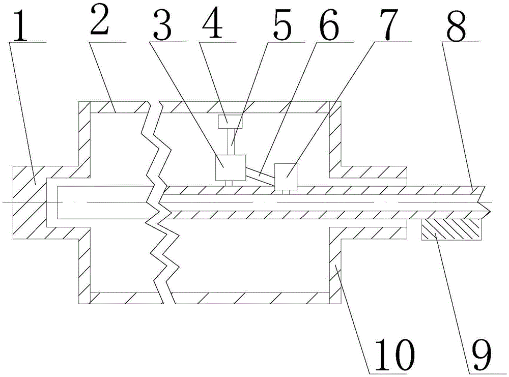
[0018] see figure 1 , the drying cylinder of the present invention comprises cylinder body 2, and the left end cap 1 that is installed on cylinder body 2 two ends and right end cap 10, the center of left end cap 1 is provided with blind hole, and the center of right end cap 10 is provided with through hole; Rigid drainage pipe 8 The left end of the drain pipe 8 is radially fixed to the central blind hole of the left end cover 1 of the drying cylinder through a bearing, and the right end of the drain pipe 8 passes through the central through hole of the right end cover 10 of the drying cylinder and is sealed and assembled with the through hole before being fixed on the frame 9; A group of separators 3 are rigidly fixed on the drain pipe 8 between the left end cover 1 and the right end cover 10 of the drying cylinder. The separators 3 all use steam-water separa...


PUM


Abstract

The invention relates to a drying cylinder condensate water draining device. The drying cylinder condensate water draining device comprises a draining pipe installed in a drying cylinder, one end of the draining pipe extends out of the drying cylinder, multiple separators are installed on the draining pipe, an inlet of each separator is connected with a winnowing pan, and an outlet of each separator is communicated with the draining pipe. By means of the winnowing pans, condensate water in the drying cylinder carries part of steam to rush into the separators, the condensate water and the steam are separated through the separators, the steam returns into the drying cylinder, only the condensate water enters the draining pipe under the action of gravity, in this way, the stable flowing state in the draining pipe is kept, and the condensate water can be conveniently drained in time. The condensate water draining device is particularly suitable for draining condensate water in medium-and-high-speed paper making machines.

Description

【Technical field】 [0001] The invention relates to the field of condensed water discharge, in particular to a drying cylinder condensed water discharge device. 【Background technique】 [0002] At present, the use of water vapor phase change in the rotating cylinder to release heat, and the external surface of the cylinder to heat the material is widely used. This kind of heating device has difficulty in discharging condensed water. In order to overcome this difficulty, people have made various efforts, especially in the pulp and paper industry. In order to improve the drying efficiency of the paper machine, the condensed water in the drying cylinder must be discharged in time. People adopt structures such as spiral grooves, spoiler rods, and rotating siphons in the drying cylinder, but the effect still cannot meet the requirements of industrial production. The reason is that none of the above measures can improve the state of unstable vapor-liquid two-phase flow in the drying ...

Claims


Application Information

Patent Timeline
Patent Type & Authority Applications(China)
IPC IPC(8): D21F5/10
CPCD21F5/10
Inventor 陈海峰刘晴顼文娟李瑞虎乔丽洁黄勋王栋
Owner SHAANXI UNIV OF SCI & TECH
Why Eureka
Try Eureka