
Blade-adjustable semi-open impeller

A semi-open blade technology, applied in the field of semi-open impeller, can solve the problems of non-adjustable blade angle, lack of blade replacement function, limited impeller working range and efficiency, etc., to achieve good adaptability, improve fan efficiency, good versatility

Active Publication Date: 2016-06-08
ESURGING TIANJIN TECH CO LTD
View PDF5 Cites 3 Cited by
  • Summary
  • Abstract
  • Description
  • Claims
  • Application Information

AI Technical Summary

Problems solved by technology

Integral type and welded type are fixed in structure and do not have the blade replacement function; the blades of the riveted impeller can be replaced, but the blade angle is fixed and cannot be adjusted, thus limiting the working range and efficiency of the impeller

Method used


Image

  • Blade-adjustable semi-open impeller
  • Blade-adjustable semi-open impeller
  • Blade-adjustable semi-open impeller

Examples


Embodiment 1

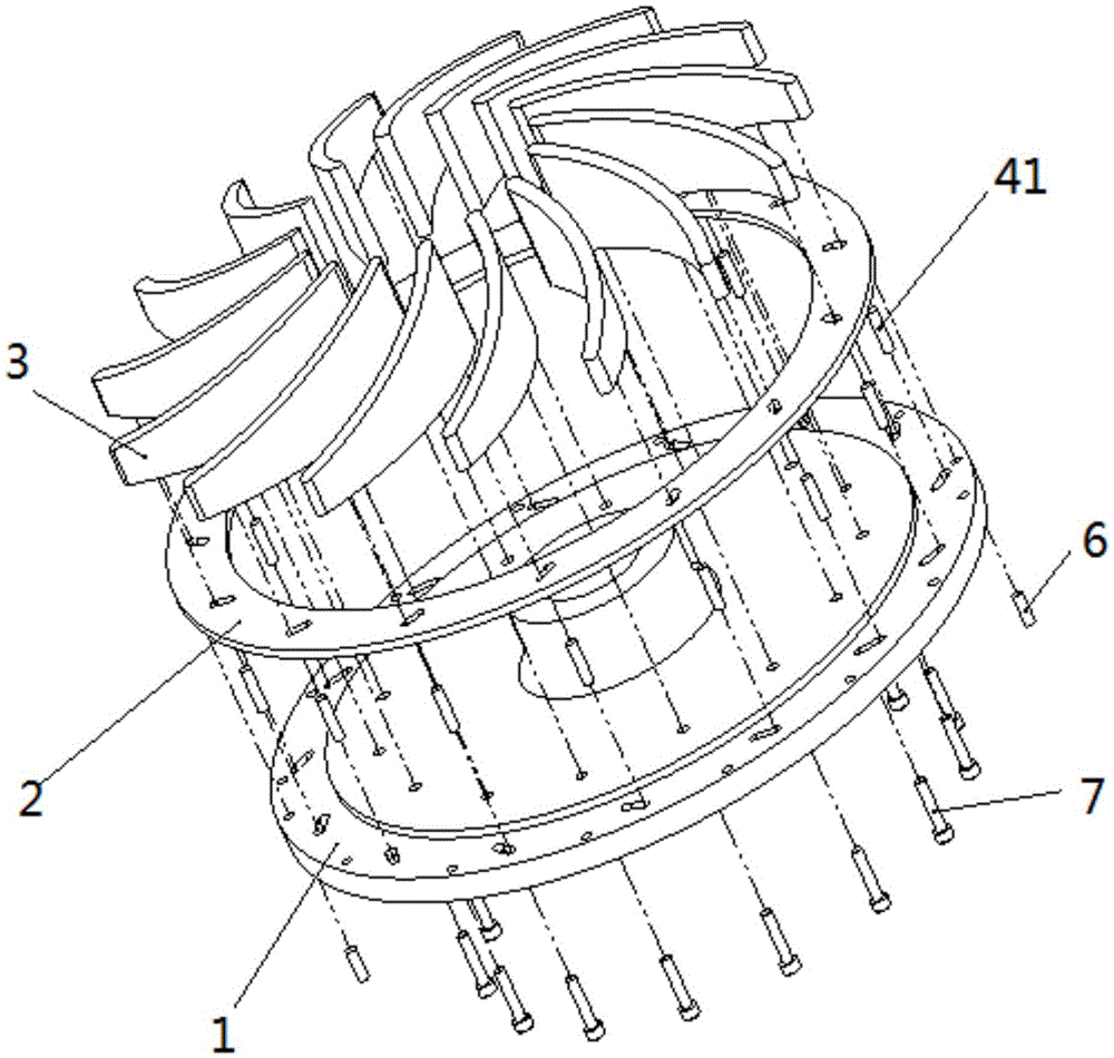
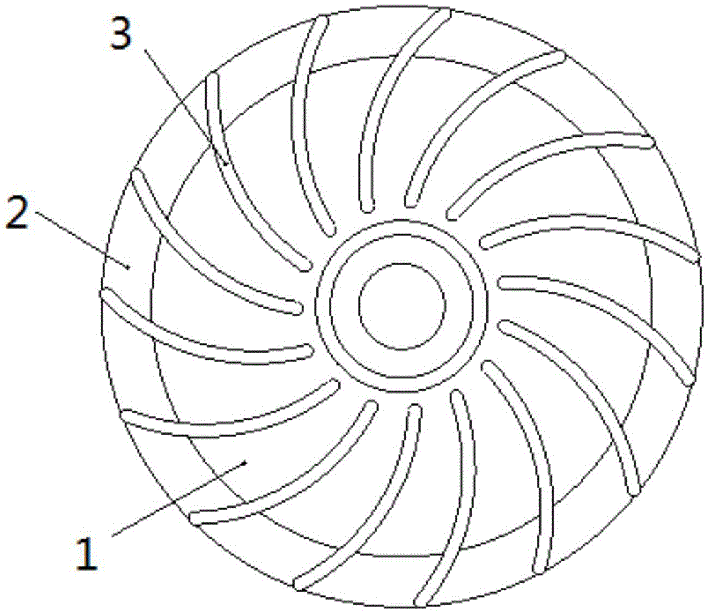
[0041] Such as Figure 1 to Figure 5 As shown, a semi-open impeller with adjustable blades includes a wheel disc 1, an adjustment ring 2 and blades 3, the front of the wheel disc 1 is provided with an annular boss, and the adjustment ring 2 can be sleeved on the boss on stage;

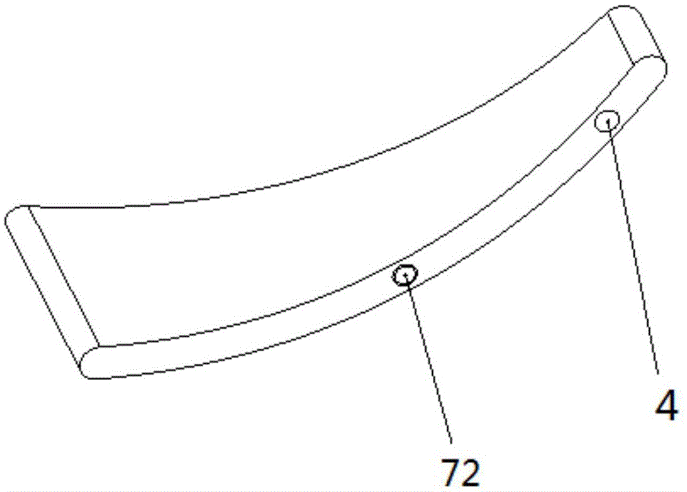
[0042] The blade 3 is provided with a positioning pin hole A4, the adjustment ring 2 is provided with a corresponding oblong hole B42, and the wheel disc 1 is also provided with an oblong groove corresponding to the oblong hole B42 and intersecting the extending direction. A43, a positioning pin A41 is arranged in the positioning pin hole A4, one end of the positioning pin A41 is fixed in the positioning pin hole A4, and the other end passes through the oblong hole B42 and is inserted into the oblong groove A43;

[0043] The roulette 1 is also provided with a positioning hole A61, and the adjustment ring 2 is also provided with a corresponding locating hole B62, which can be fixed by the pin 6; the bo...

Embodiment 2

[0053] Such as Figures 8 to 11 As shown, a semi-open impeller with adjustable blades includes a wheel disc 1, an adjustment ring 2 and blades 3, the front of the wheel disc 1 is provided with an annular boss, and the adjustment ring 2 can be sleeved on the boss on stage;

[0054] The blade 3 is provided with an oblong hole A5, and a positioning pin B51 is arranged in the oblong hole A5, one end of the positioning pin B51 is arranged in the oblong hole A5, and the other end is inserted into the adjustment ring 2 and correspondingly arranged in the pin hole B52.

[0055] When in use, the adjusting ring 2 is assembled to the annular boss of the wheel 1, and the thickness of the adjusting ring 2 is consistent with the height of the boss of the wheel 1;

[0056] One end of the positioning pin B51 is arranged in the oblong hole A5 of the blade 3, the exposed length of the other end is the depth of the corresponding pin hole B52 provided on the adjusting ring 2, and the other end ...


PUM


Abstract

The invention provides a blade-adjustable semi-open impeller which comprises an impeller disc, an adjusting ring and blades. An annular boss is arranged on the front of the impeller disc, and the adjusting ring can be mounted on the boss in a sleeving manner. When a positioning pin hole A is formed in each blade, a corresponding long round hole B is formed in the adjusting ring, a long round groove A corresponding to each long round hole B and crossed with the same in extending direction is formed in the impeller disc, a positioning pin A is arranged in each positioning pin hole A, and one end of each positioning pin A is fixed in the corresponding positioning pin hole A while the other end of the same penetrates the corresponding long round hole B to be inserted into the corresponding long round groove A. The blade-adjustable semi-open impeller has a blade detachable function, and the blade can rotate to change angle in a plane of the impeller disc when not being detached completely to realize wider working range and improve efficiency of a fan.

Description

technical field [0001] The invention belongs to the field of impellers, in particular to a semi-open impeller with adjustable blades. Background technique [0002] According to the structure, the impeller is divided into three types: open type, semi-open type and closed type. Semi-open impellers are widely used in blower equipment. At present, the processing methods of semi-open impellers mainly adopt integral type, welding type and riveting type. The integral and welded impellers are fixed in structure and do not have the blade replacement function; the blades of the riveted impeller can be replaced, but the blade angle is fixed and cannot be adjusted, which limits the working range and efficiency of the impeller. Contents of the invention [0003] In view of this, the present invention aims to provide a semi-open impeller with conveniently adjustable blades. [0004] In order to achieve the above object, technical solution of the present invention is achieved in that ...

Claims


Application Information

Patent Timeline
IPC IPC(8): F04D29/28F04D29/62
CPCF04D29/281F04D29/624
Inventor 刘志忠何毅张志华沙宏磊俞天野孙吉松郭雪峰沙佩亮王向荣潘少杰
Owner ESURGING TIANJIN TECH CO LTD
Learn More