A fast-connection structure of water hose and rigid joint

A technology of rigid joints and soft water pipes, which is applied in the direction of hose connection devices, pipes/pipe joints/pipe fittings, mechanical equipment, etc., can solve the problems of easy aging of rubber gaskets, difficulty in tightening, and high requirements for anti-seepage, and achieves convenient operation, Strong connection effect

Inactive Publication Date: 2016-06-08
广东杰邦磁能技术有限公司
View PDF7 Cites 2 Cited by
  • Summary
  • Abstract
  • Description
  • Claims
  • Application Information

AI Technical Summary

Problems solved by technology

[0005] 1. It needs to rely on rubber gaskets for sealing, and rubber gaskets are prone to aging after being heated, and water seepage is prone to occur after aging;
[0006] 2. It is necessary to rely on tightening the nut cap to exert axial pressure on the rubber washer, but because the nut cap has a tendency to loosen under the reaction of the rubber washer, the sealing performance of the rubber washer is not easy to maintain for a long time, and it needs to be larger when tightening Tightening force must rely on tools, and it is difficult to tighten with bare hands; while using tools further requires an operating space for the tool to rotate;
[0008] Due to the above reasons, the quick-connect structure of the traditional soft water pipe and rigid joint is not suitable for equipment with high anti-seepage requirements, nor is it suitable for equipment that can be assembled by hand (for example, some equipment lacks an operating surface for wrench rotation, so it is required Tighten the nut by hand)

Method used


Image

  • A fast-connection structure of water hose and rigid joint
  • A fast-connection structure of water hose and rigid joint
  • A fast-connection structure of water hose and rigid joint

Examples


Embodiment Construction

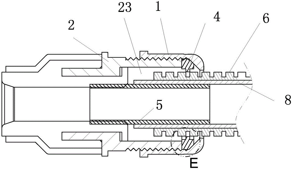
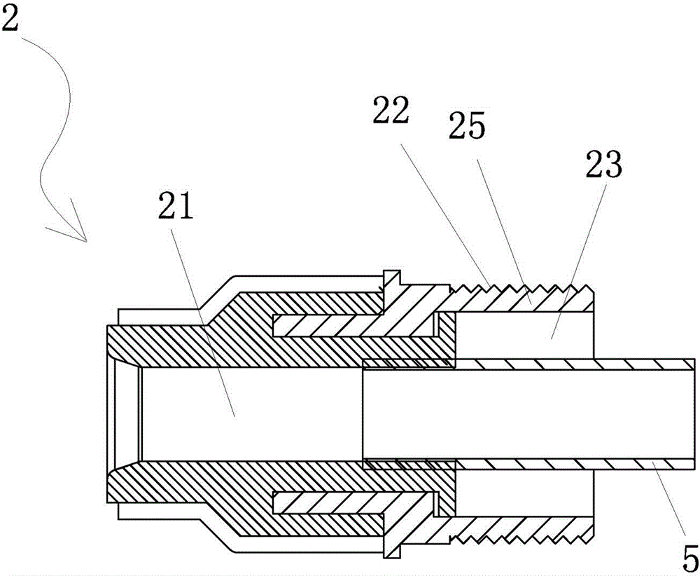
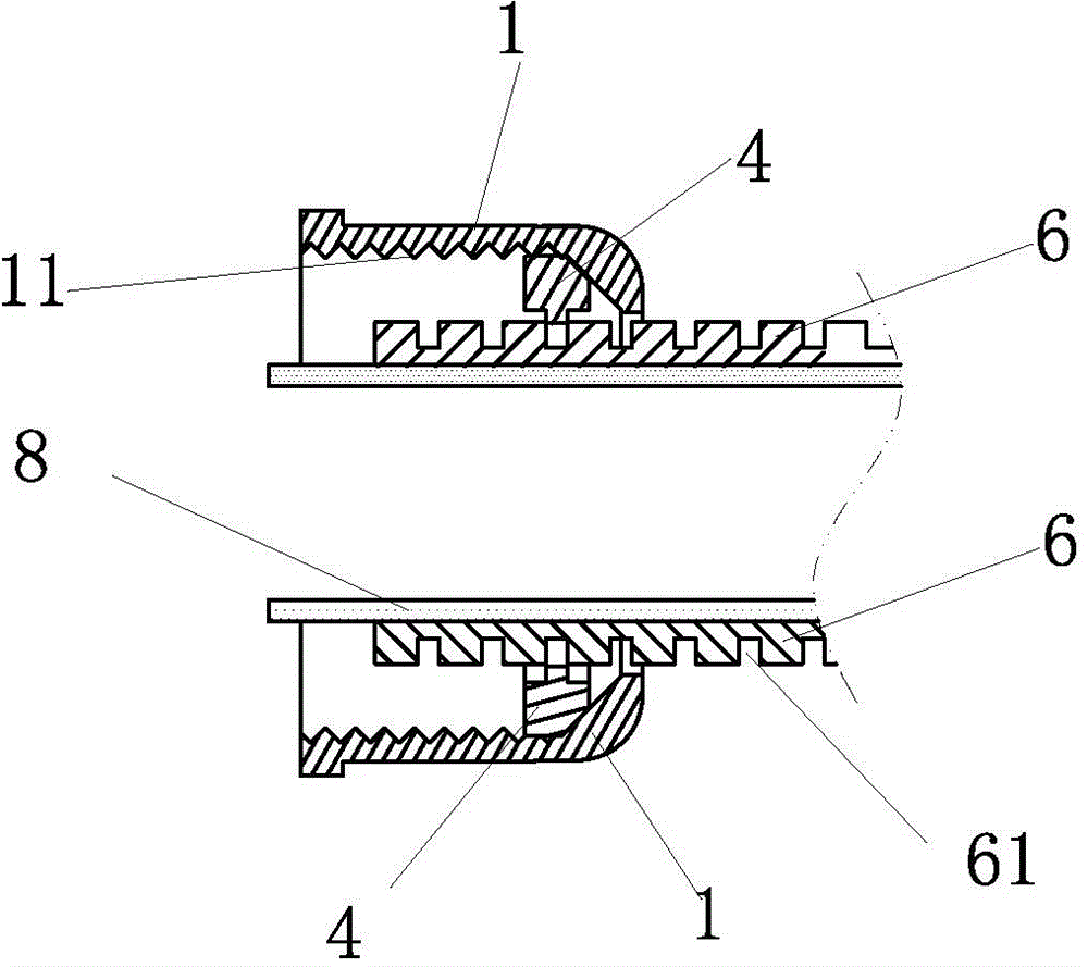
[0034] figure 1 , figure 2 , image 3 , Figure 7 As shown, the quick connection structure between the soft water pipe and the rigid joint includes a soft water pipe 8 (silicone tube), a nut cap 1, a hollow rigid joint body 2, the rigid joint body 2 is formed with a water hole 21, and the outer surface of the rigid joint body 2 The section is formed with an external thread 22, and the nut cap 1 is formed with an internal thread 11 that cooperates with the rigid joint body. After normal assembly, the nut cap 1 is screwed on the outside of the rigid joint body section 2; the cap center of the nut cap 1 is provided with a soft The hollow hole 12 through which the water pipe passes; the water hole 21 of the rigid joint body 2 is fixed and tightly connected with a rigid inner insertion tube 5, the rigid inner insertion tube is a stainless steel tube, and the inner end of the rigid inner insertion tube 5 is fixed and tightly fitted and inserted into the rigid joint In the water ...


PUM


Abstract

Disclosed is a fast-connection structure of a water hose and a rigid joint. The fast-connection structure comprises the water hose, a nut cap and a hollow rigid joint body. An outer thread is formed in an outer segment of the rigid joint body. An inner thread matched with the rigid joint body is formed in the nut cap. The nut cap is connected outside the outer segment of the rigid joint body in a screwed mode. The center of a cap cover of the nut cap is provided with a hollowed-out hole, and the water hose penetrates through the hollowed-out hole. A water passing hole is fixedly and tightly connected with a rigid inner insertion pipe. An annular gap is formed between the rigid inner insertion pipe and the outer segment of the rigid joint body. The water hose is a silicone hose. A corrugated pipe is further arranged outside the silicone hose. The tail end of the corrugated pipe and the tail end of the silicone hose are located in the annular gap. An outer segment of the rigid inner insertion pipe is movably inserted in the silicone hose and is tightened radially by the silicone hose. The corrugated pipe is sleeved with a C-shaped elastic inner buckle. A taper is formed on the inner surface of the cap cover of the nut cap. The C-shaped elastic inner buckle is located between the cap cover of the nut cap and the end face of the rigid joint body. The fast-connection structure is convenient to operate, firm in connection and good in seepage-proof effect.

Description

technical field [0001] The invention belongs to the technical field of joint structures of water flow channels, and in particular relates to a quick connection structure of a soft water pipe and a rigid joint. Background technique [0002] In order to import or export water, the water storage container is generally provided with a joint on the container wall. The joint is generally rigid, so it is called a rigid joint body. The rigid joint body is exposed outside the container wall, and its interior is hollow to form a water hole. Quickly connect (commonly known as "quick connect") the flexible water hose to the exposed rigid body to transfer water into or out of the water storage container. [0003] The quick connection structure of the traditional soft water pipe and rigid joint is as follows: the exposed part of the rigid joint body is formed with external threads, and the end of the soft water pipe is covered with a nut cap, and the center of the nut cap cap is provided ...

Claims


Application Information

Patent Timeline
Patent Type & Authority Applications(China)
IPC IPC(8): F16L33/02
Inventor 陈梓平
Owner 广东杰邦磁能技术有限公司
Why Eureka
Try Eureka