

Liquid nitrogen conveying pipeline capable of preventing water attacks
A technology for conveying pipelines and liquid nitrogen, applied in the field of low temperature applications, can solve problems such as endangering the safety of pipeline systems, pipeline vibration, low temperature water hammer, etc., and achieve the effect of eliminating pipeline vibration, avoiding hazards, and avoiding water hammer.
- Summary
- Abstract
- Description
- Claims
- Application Information
AI Technical Summary
Problems solved by technology
Method used
Image

Examples
Embodiment Construction
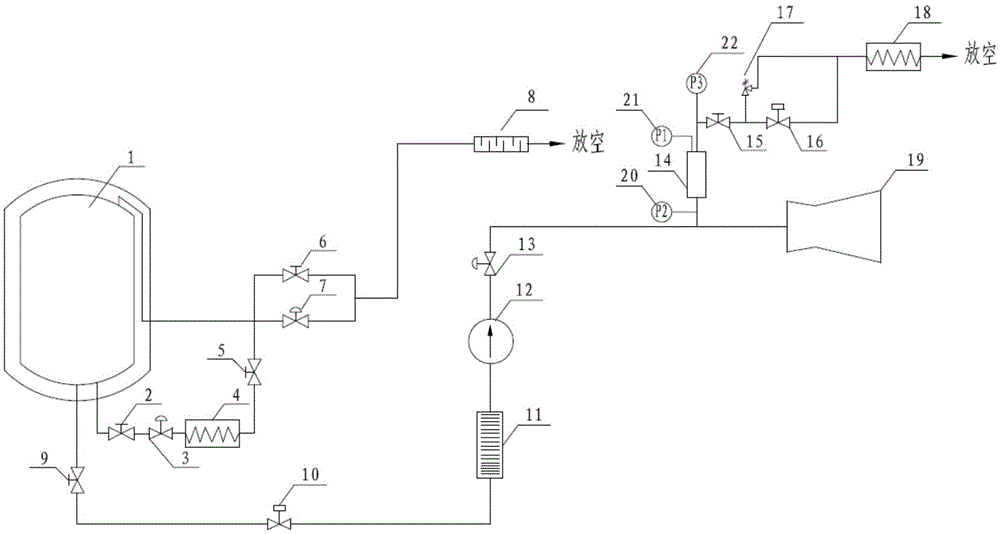
[0017] The invention provides a liquid nitrogen delivery pipeline for preventing water hammer, comprising a liquid nitrogen tank self-pressurization and pressure relief pipeline, a liquid nitrogen delivery pipeline, a liquid nitrogen fogging device, and a gas-liquid separation device; the liquid nitrogen tank self-pressurization And the pressure relief pipeline controls the pressure of the liquid nitrogen tank through the self-pressurization method to provide system backup pressure for the liquid nitrogen delivery pipeline; The regulating valve realizes the control and adjustment of the pipeline flow; the liquid nitrogen fogging device produces various spray effects; the gas-liquid separation device distinguishes the gas-liquid two-phase in the liquid nitrogen pipeline, and discharges the gaseous nitrogen in the pipeline to ensure the delivery to The terminal liquid nitrogen fogging device is single-phase liquid nitrogen.
[0018] The pressurization and pressure relief pipelin...
PUM
 Abstract
Description
Claims
Application Information