Remote-monitoring intelligent boiler system

A remote monitoring and boiler technology, applied in the general control system, control/regulation system, program control, etc., can solve the problems that failures cannot be solved in time, boilers run with diseases, and the operating status of boilers in different places cannot be grasped in time, etc., to achieve real-time Control diagnosis and treatment, reduce operating costs, and achieve the effect of diagnosis and treatment

Inactive Publication Date: 2016-06-08
CHONGQING ZHONGGUO ENERGY TECH
6 Cites 17 Cited by

AI-Extracted Technical Summary

Problems solved by technology

[0003] In the past, when the safety management of boilers was carried out, because the operation status of boilers in different places could not be grasped in time, it was generally only monitored and controlled in the on-site control room of the boiler or the DCS centralized control center connected to the factory
However, some enterprise groups have multiple companies using intelligent boi...

Abstract

The invention discloses a remote-monitoring intelligent boiler system which comprises multiple boiler control subsystems, a remote-monitoring platform and a handheld mobile terminal. The boiler control subsystems are used for collecting and uploading operating data of a boiler, and controlling the operating state of the boiler according preset parameters. The remote-monitoring platform is a computer system arranged in the remote control center, and is used for monitoring operating data of each boiler subsystem remotely, and carrying out warning and remote boiler shutdown or remote fault processing operation when faults occur. The handheld mobile terminal is used for getting access to the remote-monitoring platform, inquiring the boiler state and achieving remote boiler shutdown or remote fault processing operation. The system has remarkable advantages that remote monitoring, warning, remote boiler shutdown and remote fault processing functions are achieved, the number of boiler managing personnel can be reduced, operating cost of the boiler is reduced, and the faults are mastered in real time and can be diagnosed and processed fast.

Application Domain

Programme controlComputer control +1

Technology Topic

Embedded systemBoiler control +4

Image

  • Remote-monitoring intelligent boiler system
  • Remote-monitoring intelligent boiler system
  • Remote-monitoring intelligent boiler system

Examples

  • Experimental program(1)

Example Embodiment

[0027] The specific implementation manner and working principle of the present invention will be further described in detail below in conjunction with the accompanying drawings.
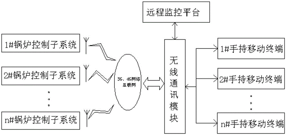
[0028] like figure 1 As shown, a remote monitoring intelligent boiler system includes multiple boiler control subsystems, a remote monitoring platform and a handheld mobile terminal, wherein:
[0029] The boiler control subsystem is installed at each boiler production site, and is used to collect and upload the operating data of the boiler, and control the operating state of the boiler according to preset parameters. Connect with a handheld mobile terminal;
[0030] The remote monitoring platform is a computer system set in the remote control center, which is used to remotely monitor the operating data of each boiler subsystem, and perform alarm, remote shutdown or remote fault handling operations when a fault occurs. Connect with the wireless communication network and the wireless communication module;
[0031] The handheld mobile terminal is a mobile phone/tablet computer carried by the relevant management personnel of each boiler production site, and is used to access the remote monitoring platform, query the status of the boiler, and realize remote shutdown or remote fault handling operations. The wireless communication module is connected. The wireless communication network is a 3G or 4G network.
[0032] See attached figure 2 , the boiler control subsystem implements data interaction with the wireless communication network and the Internet through the DTU data transmission unit.
[0033] from figure 2 It can also be seen from the figure that the boiler control subsystem includes a PLC controller, and the first data input terminal group of the PLC controller is respectively connected with a solenoid valve/pneumatic valve, a pressure transmitter, and a liquid level transmitter through a data switch , temperature transmitter and combustible gas alarm, the first flow meter and the second flow meter are respectively connected to the second data input end group of the PLC controller, and the first data output end group of the PLC is connected to the monitoring computer , the second data output terminal group of the PLC is used to realize data interaction with the remote monitoring platform, and an actuator is connected to the control signal output terminal of the PLC.
[0034] like image 3 As shown, the remote monitoring platform displays the operating status of the boiler through the simulation graph, the bar graph, and the trend graph respectively. The remote monitoring platform also sets the main process parameters and control parameters through the process parameter setting interface, wherein:
[0035] The simulation diagram is divided into a system overview diagram, a combustion system diagram, a steam-water system diagram, a flue gas system diagram and a deaeration system diagram, which are used to display the operating status of the boiler and its auxiliary equipment, various variable values, and equipment status. The variables of the alarm state are displayed in the form of changing color/flickering/automatically popping up the relevant screen, such as Figure 4 Shown:
[0036] The bar graph is used to display the working status of the PID analog control loop, and each loop can perform manual/automatic switching and upper and lower limit alarms;
[0037] The trend graph is used to display the real-time trend of the process parameters.
[0038] In this embodiment, the boiler operation data acquired by the remote monitoring platform includes furnace temperature, exhaust gas temperature, feed water temperature, steam pressure, furnace pressure, tail gas pressure, analytical gas pressure, blower pressure, induced draft fan pressure, instrument wind pressure , drum water level, boiler steam flow, boiler feed water flow, feed water regulating valve position, deaerator temperature, deaerator pressure, deaerator liquid level, deaerator inlet water regulating valve position, deaerator inlet steam Control valve position, deaerator bottom heating steam inlet control valve position, blower operating parameters, induced draft fan operating parameters, boiler feed water pump operating parameters and natural gas valve opening information.
[0039] The remote monitoring platform is also provided with an event alarm and system response module and a fault help module, wherein: the event alarm and system response module is used for displaying fault information and alarm classification; the fault help is used for when various faults occur , display a small red fault screen, and display the source of the fault and the troubleshooting method on the screen.
[0040] In this example, the fault information includes:
[0041] 1) Extremely low water level failure
[0042] When the water level in the boiler is extremely low and lacks water, through the DTU, the remote monitoring platform can collect the actual value of the boiler water level on site, and if it is lower than the set value, the system will give an alarm and send information to the user via SMS , for real-time viewing.
[0043] 2) Extremely high steam pressure failure
[0044] When the steam pressure in the boiler exceeds the set extremely high value, through the DTU, the remote monitoring platform can collect the actual value of the steam pressure of the boiler on site, and if it is lower than the set value, the system will give an alarm, which can be passed SMS to send information to users for real-time viewing.
[0045] 3) flameout failure
[0046] There is a flame inspection device in the furnace. When the furnace is off, the remote monitoring platform can collect the actual value of the on-site flame device through the DTU. When the flame is off, the system will give an alarm, and the information can be sent to the user through SMS for real-time viewing.
[0047] 4) Gas pressure failure
[0048] When the gas pressure in the pipeline is lower or higher than the set normal pressure range value, through DTU, the remote monitoring platform can collect the actual value of the gas pressure in the pipeline on site, and by comparing it with the set value, it is lower or higher than the set value. The system will give an alarm, and the information can be sent to the user through a text message for real-time viewing.
[0049] 5) Throttle failure
[0050] Damper detection feedback. When the damper fails, the remote monitoring platform can collect the actual value of the damper status through DTU. When the damper fails, the system will give an alarm, and the information can be sent to the user through SMS for real-time viewing.
[0051] 6) The tail smoke temperature is super high
[0052] 7) Others include: drum water level high and low limit alarm; gas pressure high and low alarm; blower wind pressure low alarm; gas leakage shutdown alarm; operating equipment failure alarm; Short circuit alarm; burner failure flameout alarm; high water level alarm; low water level alarm; temperature sensor failure; fault display alarm; high furnace pressure alarm; high furnace temperature alarm, etc.
[0053] In this example, when the following faults occur, the remote control center and the handheld mobile terminal can issue a shutdown command, specifically: the steam drum water level is super high, the steam drum water level is super low, the tail gas pressure is low, the tail gas pressure is high, natural gas Low pressure, high natural gas pressure, burner failure, blower failure, induced draft fan failure, flame detector failure, low blower pressure, super high furnace pressure.
[0054] The remote monitoring system in the present invention can also analyze the curve of the boiler, and make a statistical report on the historical data, which is displayed in the form of a graph, including normal monitoring parameters: furnace temperature, outlet water temperature, valve opening, pressure, etc. In addition, the system will organize and classify the alarm data, which is convenient for users to find and deal with faults.
[0055] In the actual working process of this system, the PLC and DTU communication in the boiler control subsystem send and receive data from the remote monitoring platform through the 3G and 4G networks, and the entire boiler control can be monitored and controlled on the remote monitoring platform. In the system, when failures such as low water level, high pressure, low temperature, and high temperature occur, the remote monitoring platform will send an alarm letter, and implement a detailed list of all safety alarms of the boiler system and filter alarm categories. At the same time, the platform It can send alarm information to the user's mobile phone to remind relevant personnel to quickly diagnose and deal with the alarm information;
[0056] In addition, relevant personnel can also access through mobile APP or webpage, and perform operations such as viewing data, analyzing the cause of failure, and deciding whether to shut down the furnace.
[0057] On the basis of the existing intelligent boiler control system, the present invention realizes remote monitoring, alarm, remote shutdown, and remote fault handling functions, and is not limited by space distance, and can fully understand the boiler at the remote monitoring center The operating status of the boiler can reduce the management personnel of the boiler, reduce the operating cost of the boiler, and control the phenomenon of failure in real time and realize rapid diagnosis and treatment.

PUM

no PUM

Description & Claims & Application Information

We can also present the details of the Description, Claims and Application information to help users get a comprehensive understanding of the technical details of the patent, such as background art, summary of invention, brief description of drawings, description of embodiments, and other original content. On the other hand, users can also determine the specific scope of protection of the technology through the list of claims; as well as understand the changes in the life cycle of the technology with the presentation of the patent timeline. Login to view more.

Similar technology patents

Liquid nitrogen cooling cryogenic device and implementation method for same

ActiveCN104677000AReduce equipment input costslow running cost
Owner:MATERIAL INST OF CHINA ACADEMY OF ENG PHYSICS

Parking management system

ActiveCN106228840Areduce management staffReduce management costs
Owner:浙江志诚软件有限公司

Heat recovery type water chilling unit

Owner:SHANGHAI AIRUTE AIR CONDITIONING SYST

Classification and recommendation of technical efficacy words

  • low running cost
  • reduce management staff

Method for processing sludge and kitchen wastes

Owner:INST OF URBAN ENVIRONMENT CHINESE ACAD OF SCI

Alcohol crossed circle manufacturing technique with potatoes as the main materials

ActiveCN101130790AReduce floor space and fixed asset investmentlow running cost
Owner:JIANGNAN UNIV

Parking management system

ActiveCN106228840Areduce management staffReduce management costs
Owner:浙江志诚软件有限公司
Why Eureka
Try Eureka