Method for optimizing design of straight-tooth gear shaper cutter

A technology of optimized design and gear shaping cutter, applied in the field of mechanical processing, can solve problems such as economic loss, high manufacturing cost, and low design efficiency

Inactive Publication Date: 2016-06-08
XIAN NORTH ELECTRO OPTIC TECH DEFENSE
View PDF2 Cites 2 Cited by
  • Summary
  • Abstract
  • Description
  • Claims
  • Application Information

AI Technical Summary

Problems solved by technology

The design of straight tooth shaper cutters involves a large number of space meshing calculations, calculations of transcendental equations and graphics processing, and the design verification is very complicated and cumbersome
Due to the transmission characteristics of planetary gears, it is necessary to check the machining process of the internal gear during design, and also check whether the transition curve interference occurs when the planetary gear sets mesh, which makes the design and verification of straight tooth shaper cutters more complicated and cumbersome.
The traditional design can only use a relatively rough approximate design method and repeated trial calculations. The design efficiency is low, error-prone, and parameter optimization cannot be performed.
In addition, the manufacturing cycle of gear cutters is long and the manufacturing cost is high. If rework is caused by incorrect calculation data, the construction period may be delayed, resulting in large economic losses

Method used


Image

  • Method for optimizing design of straight-tooth gear shaper cutter
  • Method for optimizing design of straight-tooth gear shaper cutter
  • Method for optimizing design of straight-tooth gear shaper cutter

Examples


Embodiment 1

[0118] A method for optimal design of straight-toothed gear-shaping cutters, at least including the following steps:

[0119] Step 1) The number of teeth of the gear shaper cutter Z 0 determination;

[0120] Step 2) Maximum variation coefficient X 0 Determination of max;

[0121] Step 3) Minimum variation coefficient X 0 Determination of min;

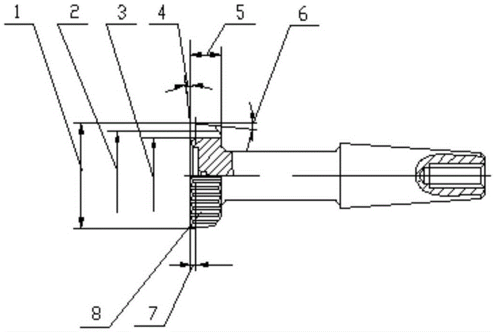
[0122] Step 4) According to the number of teeth Z in step 1) to step 3) 0 , the maximum variation coefficient X 0 max, minimum variation coefficient X 0 min, calculate the distance from the basic section of the gear shaper cutter to the front end face, and the tooth profile parameters of the original section, front end face, and inspection section of the gear shaper cutter. In this step, the method of calculating the distance from the basic section of the gear shaping cutter to the front end surface, and the tooth shape parameters of the original section of the gear shaping cutter, the front end surface, and the inspection sectio...

Embodiment 2

[0125] A method for optimal design of straight-toothed gear-shaping cutters, at least including the following steps:

[0126] Step 1) The number of teeth of the gear shaper cutter Z 0 OK for:

[0127] a) The number of teeth of the gear shaper cutter is first according to the formula Z 0 = Z 2 / 1.5~Z 2 / 2 for primaries; where Z 2 For the cut internal gear;

[0128] b) Select the number of teeth that has no common denominator with the number of teeth of the gear grinding machine indexing worm gear pair and the gear to be cut from the number of teeth in the primary selection;

[0129] c) Choose the most number of teeth from the number of teeth that have no common denominator.

[0130] Step 2) Maximum variation coefficient X 0 Determination of max:

[0131] The step 2) maximum variation coefficient X 0 The determination of max is limited by the sharpening of the tooth tip of the gear shaper, the limit of the cut-in top cut, the limit of the negative mesh angle phenomenon,...

Embodiment 3

[0137] On the basis of Example 2, the limit of the sharpening of the tooth tip of the gear shaping cutter in the step 2): the minimum tooth tip width allowed by the gear shaping cutter [S a0 ] min Calculate according to the formula:

[0138] [S a0 ] min = S a0y A c

[0139] In the formula: A c ——Pressure Angle Coefficient A c =0.55 / (tanα) 0.5915

[0140] S a0y ={m[-0.032+0.0065mZ 0 -6.8X10 -5 x(mZ 0 ) 2 +3.2x10 -7 x(mZ 0 ) 3 ]+[0.027-0.0026mZ 0 +5.6x10 -5 (mZ 0 ) 2 -3.6x10 -7 x(mZ 0 ) 3 ]} 1 / 2

[0141] Maximum variation coefficient (X 0 ) max , which can be calculated according to the restrictive condition of tooth top becoming sharper by the following formula:

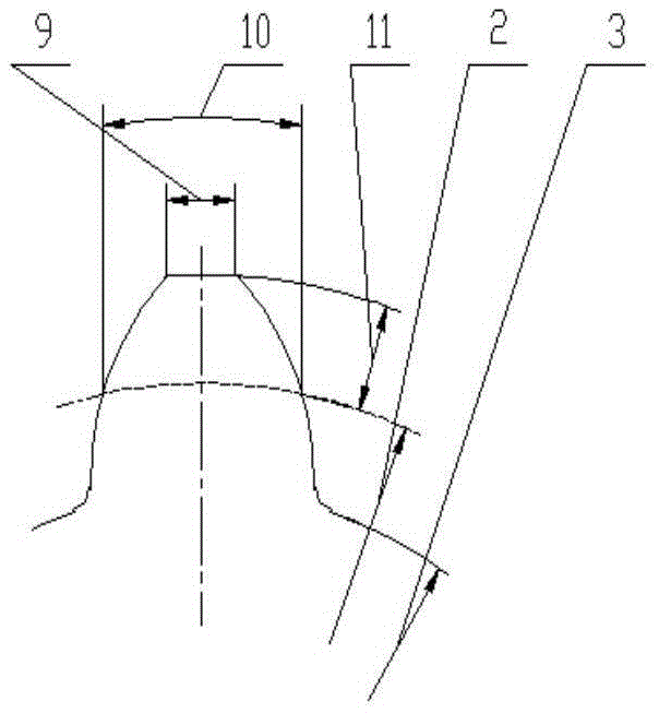
[0142] S a0 =[π+4X 0 tanα / Z 0 +(invα-invα a0 )]r a0

[0143] In the formula: S a0 ——The actual width of the top edge of the gear shaping cutter

[0144] r a0 —— Radius of tip circle of gear shaping cutter

[0145] α——the index circle pressure angle of the gear shaper cutter

[01...


PUM


Abstract

The invention relates to a method for optimizing design of a straight-tooth gear shaper cutter. The method is characterized by at least comprising the following steps that 1, the number Z0 of teeth of the gear shaper cutter is determined; 2, the maximum modification coefficient X0max is determined; 3, the minimum modification coefficient X0min is determined; 4, according to the number Z0 of the teeth, the maximum modification coefficient X0max and the minimum modification coefficient X0min in the steps from first to third, the distance from the fundamental section of the gear shaper cutter to the front end face of the gear shaper cutter and tooth profile parameters of the original section, the front end face and the inspection section of the gear shaper cutter are calculated; 5, the gear shaper cutter is designed according to the parameters calculated in the fourth step, and machining is conducted on a cut internal gear. The straight-tooth gear shaper cutter designed through the method has the advantages of being high in precision, reliability and efficiency, the manufacturing cycle of a gear cutter is shortened, and the manufacturing cost is reduced.

Description

technical field [0001] The invention relates to a straight-toothed gear-shaping cutter, which is a method for optimizing the design of a straight-toothed gear-shaping cutter. It belongs to the field of mechanical processing. Background technique [0002] The gear mechanism is an important part of the transmission mechanism and is the most widely used transmission form. The planetary gear reduction mechanism of a certain product is the core component of the optical zoom system of the product. In view of the structural characteristics of the optical control device, the structural size of the planetary gear parts is small, and the precision requirements are all grade 6, which is difficult to process. Due to the limitation of the part structure of this product, the standard straight tooth shaper cutter cannot process it, and only a special straight tooth shaper cutter suitable for processing this type of gear parts can be designed. [0003] The straight tooth shaper cutter is ...

Claims


Application Information

Patent Timeline
Patent Type & Authority Applications(China)
IPC IPC(8): G06F17/50
CPCG06F30/17G06F2119/18
Inventor 张勇程会民李时威杨永娟
Owner XIAN NORTH ELECTRO OPTIC TECH DEFENSE
Why Eureka
Try Eureka