Eureka AIR delivers breakthrough ideas for toughest innovation challenges, trusted by R&D personnel around the world.

Paying off apparatus

A technology of pay-off device and traction device, which is applied in the manufacture of electrical components, circuits, cables/conductors, etc. It can solve the problems of difficult operation, complex structure, and difficulty in flattening and straightening aluminum wires, and achieves the extension of walking path and volume Small, manageable effects

Inactive Publication Date: 2016-06-08
LUOYANG DAYUAN CABLE
View PDF4 Cites 0 Cited by
  • Summary
  • Abstract
  • Description
  • Claims
  • Application Information

AI Technical Summary

Problems solved by technology

A single aluminum wire is poured and formed in the casting workshop, then coiled into a disc shape, and then transported to other processing workshops, and then multiple aluminum wires are twisted into one strand through a frame-type stranding machine. Before stranding the wires, it is necessary to first To stretch out the coiled aluminum wire, the existing pay-off equipment is complex in structure, difficult to operate, and it is not easy to flatten and straighten the curved aluminum wire

Method used


Image

  • Paying off apparatus

Examples


Embodiment Construction

[0015] The technical solutions of the present invention will be further described in detail below in conjunction with the accompanying drawings and embodiments.

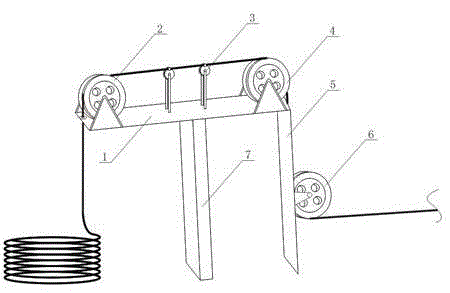
[0016] Such as figure 1 As shown, a pay-off device includes a bracket and a traction device fixed on the bracket. The bracket is an approximately "7"-shaped structure composed of a top plate 1 and a side plate 5 vertically connected. The traction device includes a traction wheel A2 , the traction wheel B4, the traction wheel C6 and the guide wheel 3, the traction wheel A2 and the traction wheel B4 are fixed on the upper surface of the top plate 1 through the support frame respectively, and the wheel grooves on the traction wheel A2 and the traction wheel B4 are opposite to each other , the top plate 1 is also provided with a guide wheel 3 between the traction wheel A2 and the traction wheel B4; the traction wheel C6 is fixed on the outer surface of the side plate 5 through a support frame.

[0017] The wheel groove ...


PUM


Abstract

The invention discloses a paying off apparatus. The apparatus comprises a support and a traction device fixedly arranged on the support. The support is an approximate ''7''-shaped structure formed through vertically connecting a top plate and a side plate. The traction device comprises a traction wheel A, a traction wheel B, a traction wheel C and a guiding wheel. The traction wheel A and the traction wheel B are fixedly arranged on an upper surface of the top plate through a support frame respectively. Wheel grooves on the traction wheel A and the traction wheel B are opposite to each other. The top plate is provided with the guiding wheel located between the traction wheel A and the traction wheel B. The traction wheel C is fixedly arranged on an outer side surface of the side plate through the support frame. During usage, one end of an aluminum wire successively winds and passes through the traction wheel A, the guiding wheel, the traction wheel B and the traction wheel C and is connected to the traction device so as to realize unfolding and placing of a disc-shape aluminum wire. In the invention, a walking path of the aluminum wire is prolonged, an flattening effect is increased and the apparatus size is small so that an occupied area in a workshop is saved and workshop management is convenient.

Description

technical field [0001] The invention belongs to the field of cable production, in particular to a wire pay-off device. Background technique [0002] At present, the cores of most aluminum cables are usually formed by splicing multiple single aluminum wires. A single aluminum wire is poured and formed in the casting workshop, then coiled into a disc shape, and then transported to other processing workshops, and then multiple aluminum wires are twisted into one strand through a frame-type stranding machine. Before stranding the wires, it is necessary to first The aluminum wire that is coiled into a disc shape is stretched out, and the existing wire-releasing equipment is complicated in structure, difficult to operate, and it is not easy to flatten and straighten the curved aluminum wire. Contents of the invention [0003] In order to solve the problems existing in the prior art, the object of the present invention is to provide a wire pay-off device. [0004] In order to r...

Claims


Application Information

Patent Timeline
IPC IPC(8): H01B13/00
Inventor 晋备战赵朋森
Owner LUOYANG DAYUAN CABLE
Why Eureka
Eureka Blog
Learn More