Eureka AIR delivers breakthrough ideas for toughest innovation challenges, trusted by R&D personnel around the world.

Ultra-high-temperature and ultra-low-emission pulse dust collector

A pulse dust collector and ultra-high temperature technology, applied in chemical instruments and methods, dispersed particle filtration, gas treatment, etc., can solve problems such as high energy consumption, and achieve the effect of extending the walking path, improving the dust removal effect, and improving the blocking effect.

Pending Publication Date: 2019-04-02
CHONGQING BW ENVIRONMENTAL PROTECTION ENG EQUIP CO LTD
View PDF13 Cites 0 Cited by
  • Summary
  • Abstract
  • Description
  • Claims
  • Application Information

AI Technical Summary

Problems solved by technology

[0004] The present invention provides an ultra-high temperature and ultra-low emission pulse dust collector to solve the problem of high energy consumption during operation due to the use of filter bags in the prior art

Method used


Image

  • Ultra-high-temperature and ultra-low-emission pulse dust collector
  • Ultra-high-temperature and ultra-low-emission pulse dust collector
  • Ultra-high-temperature and ultra-low-emission pulse dust collector

Examples


Embodiment 1

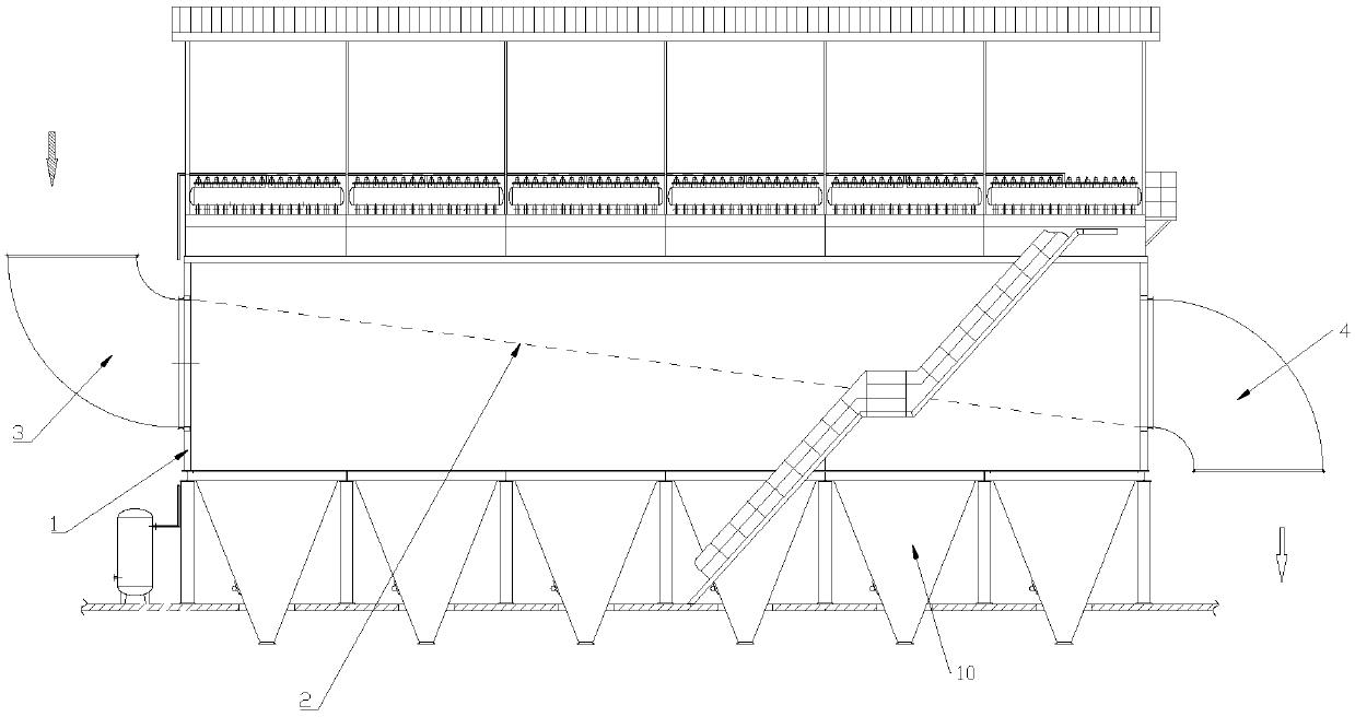
[0018] Such as figure 1 As shown, the present invention proposes a pulse dust collector with ultra-high temperature and ultra-low emission, comprising: dust removal box 1, partition plate 2, metal filter cartridge (not shown in the figure), air inlet pipe 3 and exhaust pipe 4, dust removal The box 1 is provided with an inner cavity, and a partition plate 2 is installed on the inner wall of the cavity. The partition plate 2 divides the inner cavity into an upper chamber and a lower chamber, an air inlet pipe and an exhaust pipe. There are at least three metal filter cartridges located in the vertical direction, the bottom of each metal filter cartridge communicates with the lower chamber, and the top of each metal filter cartridge is provided with a through hole that only communicates with the upper chamber. For air to pass through, an air inlet pipe 3 is installed at one end of the dust removal box 1, and the air inlet pipe 3 communicates with the lower chamber. At the positi...

Embodiment 2

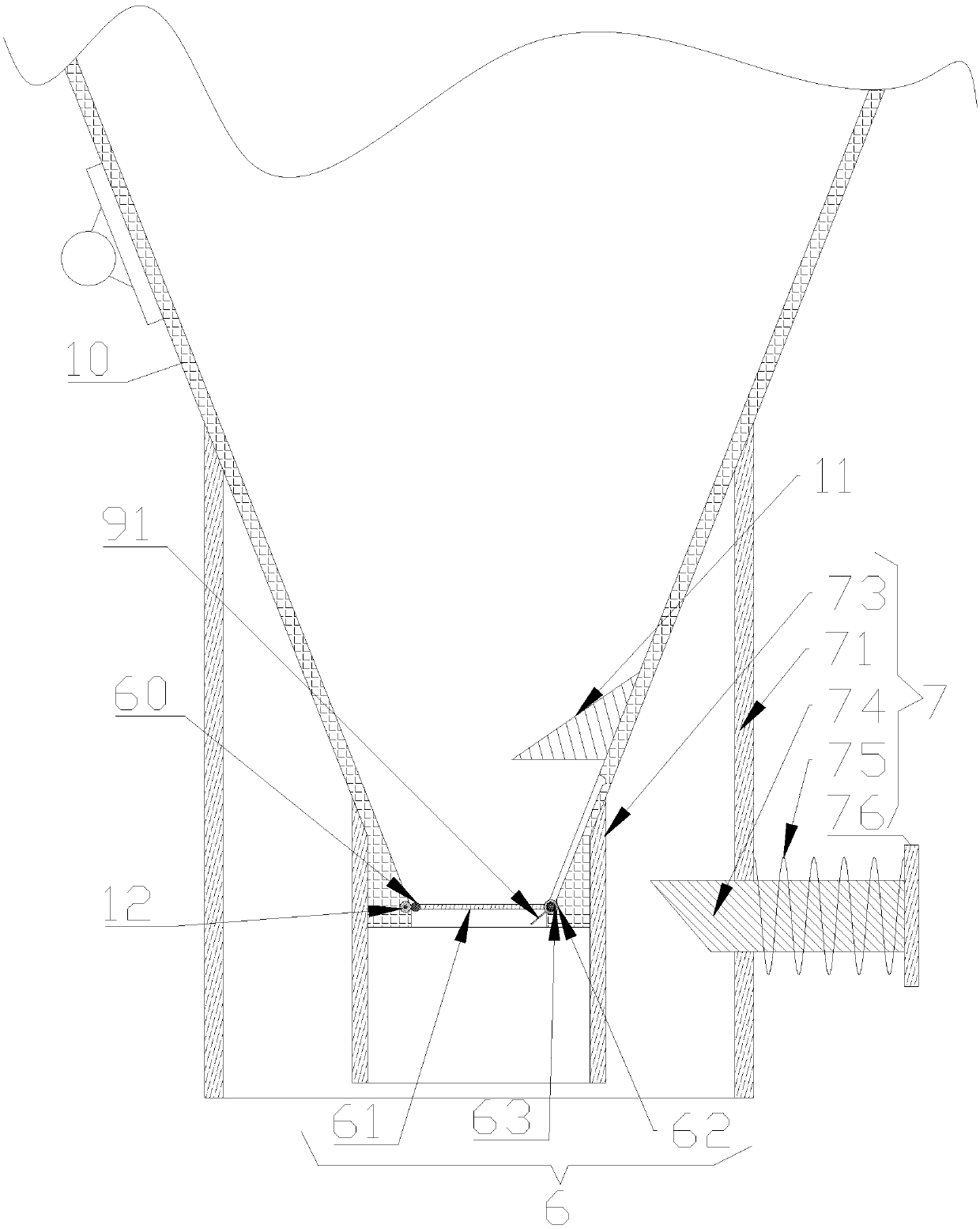
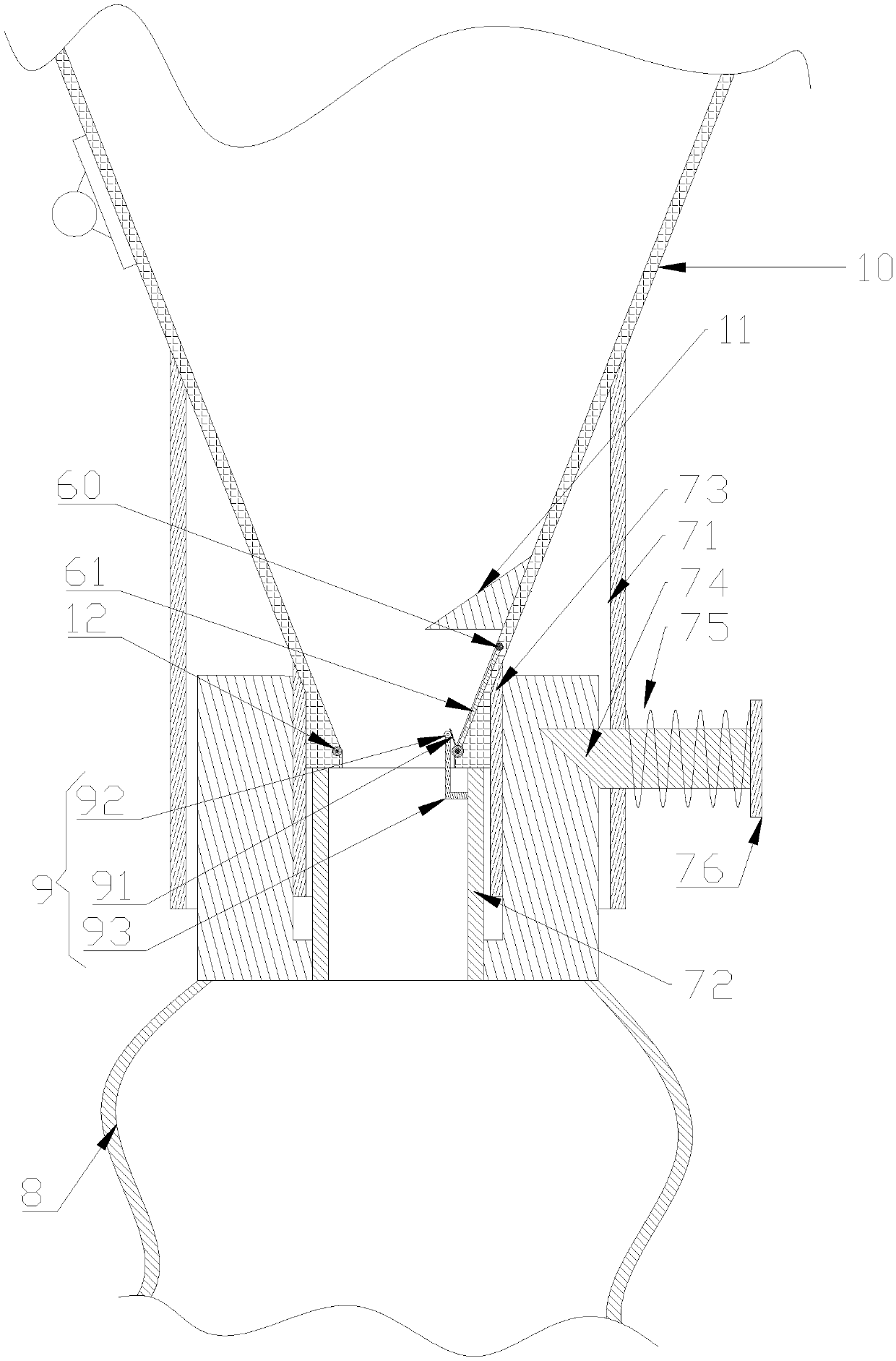
[0021] Such as figure 2 as well as image 3 As shown, the difference between this embodiment and Embodiment 1 is only that: in order to realize smooth discharge, an ash hopper 10 is installed at the bottom of the dust removal chamber to realize the deposition of dust, and an opening and closing mechanism 6 is installed at the bottom of the ash hopper 10 to realize Only after the ash container 8 is communicated with the ash hopper 10, the ash discharge pipe 5 is opened, which avoids the downward movement of dust in the ash hopper 10 when the ash container 8 is not installed.

[0022] The bottom of the dust removal chamber is connected to the large ends of several ash hoppers 10. The small ends of the ash hoppers 10 are located below the large ends of the ash hoppers 10. There are ash discharge pipes 5 connected to the small ends of the ash hoppers 10. The ash discharge pipes 5 are equipped with a switch for opening and closing. The opening and closing mechanism 6 of the ash d...


PUM


Abstract

The invention provides an ultra-high-temperature and ultra-low-emission pulse dust collector. The ultra-high-temperature and ultra-low-emission pulse dust collector comprises a dust collection box, apartition plate, metal filtering drums, an air inlet pipe and an air exhaust pipe, wherein an inner cavity is arranged in the dust collection box; the partition plate is arranged on the inner walls ofthe inner cavity, separates the inner cavity into an upper chamber and a lower chamber and penetrates through at least three metal filtering drums which are located in a vertical direction; the bottom end of each metal filtering drum communicates with the lower chamber; the top end of each metal filtering drum is provided with a through hole communicating with the upper chamber; through holes only allow air to pass through; one end of the dust collection box is provided with the air inlet pipe which communicates with the lower chamber; the position where one end, far away from the dust collection box, of the air inlet pipe is located is higher than the position where the end part, connected with the dust collection box, of the air inlet pipe is located; one end, far away from the air inlet pipe, of the dust collection box is provided with the air exhaust pipe which communicates with the upper chamber; and the air exhaust pipe communicates with the upper chamber and is inclined downward. The ultra-high-temperature and ultra-low-emission pulse dust collector provided by the invention solves the problem of reduced dust collection effect due to location of the air inlet pipe in a horizontal direction.

Description

technical field [0001] The invention relates to a dust collector, in particular to an ultra-high temperature and ultra-low emission pulse dust collector. Background technique [0002] In the prior art, the ultra-high temperature exhaust gas dust removal device includes: a cooling pretreatment area, a gravity dust removal area, an exhaust gas treatment area, and a fine dust removal area arranged on the cooling group frame. The cooling pretreatment area includes a cooling tube group, a cooling tube group It includes a number of heat exchange tube bundles, and an inlet head is connected above the cooling tube group; the gravity dust removal area includes a confluence box room, and a first-stage ash storage bucket is arranged below the confluence box room; the fine dust removal area includes a flow equalization box , a number of baffles are arranged in the flow equalization box, a secondary ash storage bucket is connected under the flow equalization box, a filter box is connecte...

Claims


Application Information

Patent Timeline
Patent Type & Authority Applications(China)
IPC IPC(8): B01D46/24B01D46/00B01D46/44
CPCB01D46/2411B01D46/448B01D2258/02B01D46/71
Inventor 任俊
Owner CHONGQING BW ENVIRONMENTAL PROTECTION ENG EQUIP CO LTD
Why Eureka
Eureka Blog
Learn More