automatic milk machine
A technology for automatic flushing and flushing of milk chambers, applied in beverage preparation devices, household appliances, applications, etc., can solve problems such as milk powder agglomeration, milk powder and water do not have enough time to mix, etc., to achieve extended walking path, simple structure, and improved The effect of mixing effects
- Summary
- Abstract
- Description
- Claims
- Application Information
AI Technical Summary
Problems solved by technology
Method used
Image
Examples
Embodiment 1
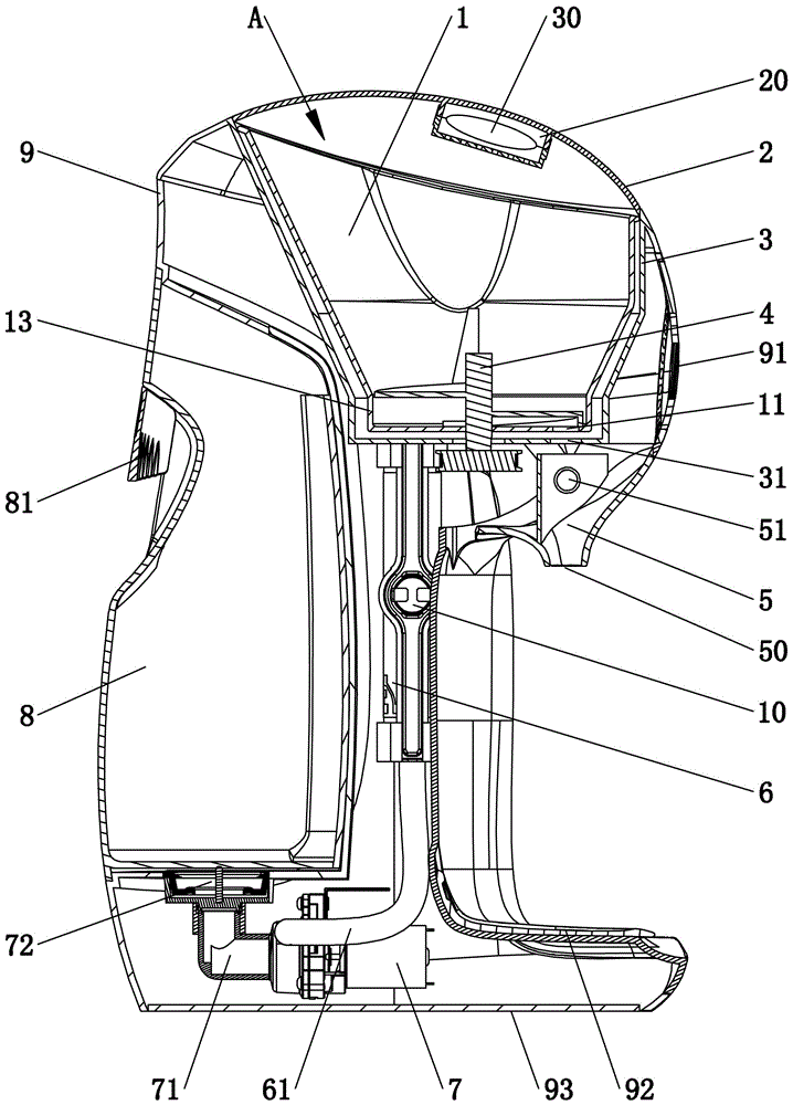
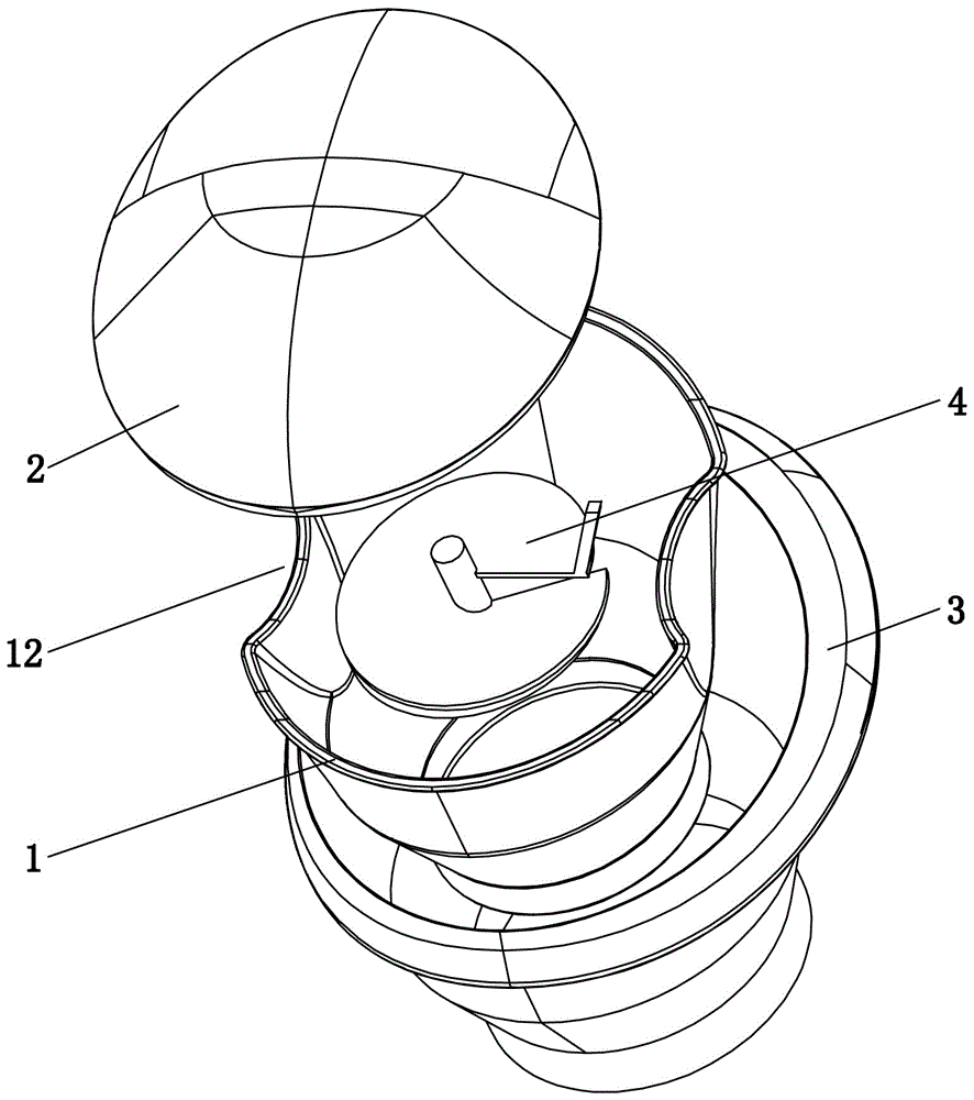
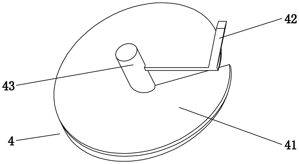
[0039] Embodiment one, see Figure 1 to Figure 3As shown, an automatic milk machine includes a milk powder feeding device, and the milk powder feeding device includes a milk powder storage box 1, a stirring paddle 4 and a control motor (not shown in the figure), and the bottom of the milk powder storage box 1 is provided with a first Feed port 11, stirring paddle 4 is arranged in the lower part of the milk powder storage box 1 in rotation; the stirring paddle includes a central shaft 43 and a powder feeding screw blade 41, and the powder feeding screw blade 41 is arranged outside the central shaft 43, and the bottom of the powder feeding screw blade 41 A cover surface 45 for closing the first feeding port 11 is provided, and a pusher retaining surface 44 is provided between the cover surface 45 and the spiral surface at the bottom of the powder feeding screw blade 41; The outer diameter of the spiral blade 41 is suitable for the feeding sleeve 13 .
[0040] The stirring paddl...
Embodiment 2
[0052] Embodiment two, the difference with embodiment one is: see Figure 7 As shown, the moisture-proof agent storage structure includes a tank body 21 and a top cover 27, the top surface of the tank body 21 is open to the outside of the cover body 2, the inner surface of the tank body 21 is provided with a vent hole 26 connected to the milk powder storage area A, and the top cover 27 is sealingly connected with the opening of the tank body 21.
Embodiment 3
[0053] Embodiment three, the difference with embodiment one is: see Figure 8 As shown, one end of the cover body 2 is hinged with the fuselage shell 9, the other end of the cover body 2 is provided with a hook contact 28, and the fuselage shell 9 is provided with a self-locking switch 40 corresponding to the other end of the cover body 2, and the self-locking switch 40 There is a locking hook 401 snapped together with the hooked contact 28 .
[0054] see Figure 8 As shown, the self-locking switch 40 is in the unlocked state (that is, the lock hook 401 is opened and protrudes out of the self-locking switch 40), the cover body 2 is in a free state, and can be opened or closed along the direction of the R arrow; Press the cover 2, the hooked contact 28 of the cover presses the locking hook 401 of the self-locking switch 4, so that the locking hook 401 retracts toward the inner direction of the self-locking switch 40, the locking hook 401 closes and hooks the hooked contact 28...
PUM
 Abstract
Description
Claims
Application Information
 - R&D
- Intellectual Property
- Life Sciences
- Materials
- Tech Scout
- Unparalleled Data Quality
- Higher Quality Content
- 60% Fewer Hallucinations
Browse by: Latest US Patents, China's latest patents, Technical Efficacy Thesaurus, Application Domain, Technology Topic, Popular Technical Reports.
© 2025 PatSnap. All rights reserved.Legal|Privacy policy|Modern Slavery Act Transparency Statement|Sitemap|About US| Contact US: help@patsnap.com


