Capacitive charging DC breaker and application thereof

A DC circuit breaker and capacitor charging technology, which is applied in the direction of DC network circuit devices, circuit devices, emergency protection circuit devices, etc., can solve the problem of high cost of the main branch circuit, high cost of valve components of power electronic devices, and inability to realize fast reclosing, etc. problem, to achieve the effect of eliminating the inductance-capacitance resonance problem, increasing the speed, and reducing the cost of semiconductors

Active Publication Date: 2016-06-08
HUAZHONG UNIV OF SCI & TECH
View PDF5 Cites 34 Cited by
  • Summary
  • Abstract
  • Description
  • Claims
  • Application Information

AI Technical Summary

Problems solved by technology

This type of DC circuit breaker realizes the isolation of DC faults by transferring the fault current to the capacitor 5 in the event of a DC fault. It can overcome the defects of high cost of the main branch of the conventional hybrid high-voltage DC circuit breaker. The current inductance 2 and the capacitor 5 form a series circuit. On the one hand, there is an inductance-capacitance resonance during the breaking of the fault current, and it takes a long time to turn off the DC fault current. Charged to a high-voltage state, it is necessary to discharge the capacitor 5 before reclosing can be realized, and it takes a certain time to discharge the capacitor 5, so the above scheme cannot realize fast reclosing, and its power electronic device valve group 4 is all controlled by a fully controlled Composition of power electronic devices, the cost of valve group 4 of power electronic devices is relatively high

Method used


Image

  • Capacitive charging DC breaker and application thereof
  • Capacitive charging DC breaker and application thereof
  • Capacitive charging DC breaker and application thereof

Examples


Embodiment Construction

[0049] In order to make the object, technical solution and advantages of the present invention clearer, the present invention will be further described in detail below in conjunction with the accompanying drawings and embodiments. It should be understood that the specific embodiments described here are only used to explain the present invention, not to limit the present invention. In addition, the technical features involved in the various embodiments of the present invention described below can be combined with each other as long as they do not constitute a conflict with each other.

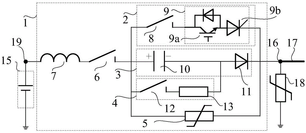
[0050] figure 2 Shown is a schematic diagram of the circuit structure of the capacitor charging DC circuit breaker 1 according to an embodiment of the present invention. figure 2 Among them, the DC circuit breaker 1 is mainly composed of an auxiliary branch 2 and a main branch 3 connected in parallel, wherein the auxiliary branch 2 is composed of a first mechanical switch 8 and a power electr...


PUM


Abstract

The invention discloses a capacitive charging DC breaker. The capacitive charging DC breaker comprises an auxiliary branch and a primary branch, which are connected with each other in parallel, wherein the auxiliary branch is formed by connecting a first mechanical switch and a power electronic device valve bank in series; and the primary branch is formed by connecting DC capacitors and a diode valve bank in series. A DC fault current is isolated through the charging effect of a DC to each DC capacitor during a DC fault period. A reclosing instruction is sent out only when the condition that a line side current of the DC breaker is higher than a threshold is detected in the reclosing process. The invention further discloses the DC breaker. The primary branch is formed by connecting multiple groups of DC capacitors which are connected with one another in series and the mechanical switches in parallel. The invention further discloses a control method for carrying out fast reclosing on the DC breaker correspondingly. The defect that inductance-capacitance oscillation is easily formed by the DC capacitors and line inductor of the existing DC breaker can be avoided; opening and closing of the DC fault current are stable and reliable; and fast reclosing can be achieved.

Description

technical field [0001] The invention belongs to the technical field of electric power transmission and distribution, and more specifically relates to a capacitor charging DC circuit breaker and its application in DC fault isolation. Background technique [0002] With the development of modular multilevel converters, the use of modular multilevel converters to construct DC power grids has become a hot spot in the power industry in recent years. The DC power grid needs to interconnect the DC transmission lines on the DC side. When a DC fault occurs, it is necessary to quickly isolate the faulty line to avoid the voltage collapse of the DC grid. For this reason, the DC circuit breaker is an indispensable device for large-scale DC power grids. [0003] The solid-state switching branch circuit breaker is a typical DC circuit breaker, which is composed of a large number of fully-controlled power electronic devices connected in series. It is subtle, but the main defect of this sol...

Claims


Application Information

Patent Timeline
Patent Type & Authority Applications(China)
IPC IPC(8): H02J1/00H02H3/087
CPCH02H3/087H02J1/00
Inventor 林卫星周猛文劲宇
Owner HUAZHONG UNIV OF SCI & TECH
Why Eureka
Try Eureka