Aerogenerator current transformer and control method thereof
A technology of wind power generator and control method, which is applied in the direction of wind power generation, single-network parallel feeding arrangement, etc., can solve the problems of increasing the work of designers and increasing the design cost of converters, etc., so as to save equipment and labor costs, and reduce components and the design cost, the effect of optimizing the topology
- Summary
- Abstract
- Description
- Claims
- Application Information
AI Technical Summary
Problems solved by technology
Method used
Image
Examples
Embodiment 1
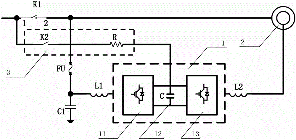
[0034] as attached figure 2As shown, a specific embodiment of a wind power generator converter includes: a grid-connected contactor K1 and a converter 1 , and the converter 1 includes a grid-side converter 11 and a machine-side converter 13 . The grid-side converter 11 is connected to the grid-connected contactor K1, the machine-side converter 13 is connected to the generator 2, and the stator side (stator winding) of the generator 2 is connected to the grid-side converter 11 by sharing the grid-connected contactor K1 to the grid. The wind power generator converter also includes: a pre-charging circuit 3 , a grid-side reactor L1 and a generator-side reactor L2 . The pre-charging circuit 3 includes a pre-charging contactor K2 and a current limiting resistor R, and the converter 1 also includes a DC bus 12 . The incoming terminal of the grid-connected contactor K1 is connected to the grid, and the other end of the grid-connected contactor K1 is divided into two terminals, one...
Embodiment 2
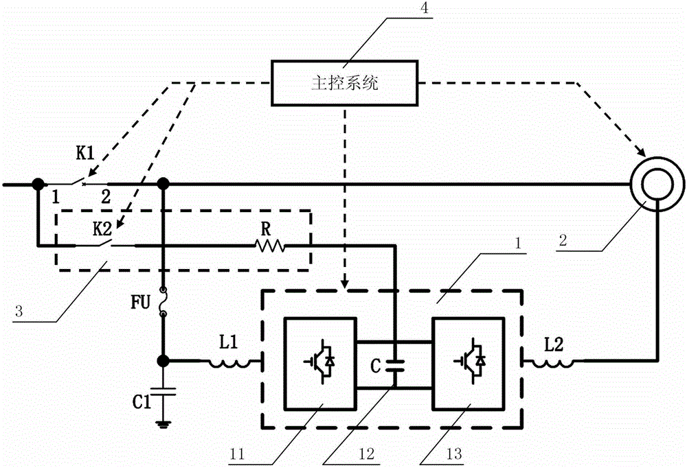
[0038] As another specific embodiment of the present invention, as attached image 3 As shown, the wind power generator converter further includes a main control system 4, and the main control system 4 is respectively connected with the converter 1, the generator 2, the grid-connected contactor K1, and the pre-charging contactor K2. Before the start of the wind turbine, the grid voltage of the box transformer is sent to the first terminal of the grid contactor K1, and when the grid voltage is detected to be normal, the pre-charging contactor K2 is turned on to charge the DC bus 12 of the converter 1 , to complete the establishment of the intermediate voltage. The main control system 4 of the wind power generator controls the rotation of the generator 2 near the synchronous speed, and starts the grid-side converter 11 of the converter 1, so that the grid-side converter 11 works in the voltage open-loop mode and controls the grid voltage. Phase-locking, when the output voltage ...
Embodiment 3
[0040] A specific embodiment of a wind power generator converter control method, comprising the following steps:
[0041] S100: Before the start of the wind turbine, the grid voltage of the box transformer is transmitted to the first terminal of the grid contactor K1, and when the grid voltage is detected to be normal, the pre-charging contactor K2 is turned on, which is the DC bus of the converter 1 12 charging to complete the establishment of the intermediate voltage;
[0042] S101: The main control system 4 of the wind power generator controls the rotation of the generator 2 near the synchronous speed, and starts the grid-side converter 11 of the converter 1, so that the grid-side converter 11 works in a voltage open-loop mode and is connected to the power grid. The voltage is phase-locked; the voltage open-loop method is to control the amplitude and frequency of the inverter output voltage of the grid-side converter 11 through direct setting to meet the grid-connected requ...
PUM
 Abstract
Description
Claims
Application Information
 - R&D
- Intellectual Property
- Life Sciences
- Materials
- Tech Scout
- Unparalleled Data Quality
- Higher Quality Content
- 60% Fewer Hallucinations
Browse by: Latest US Patents, China's latest patents, Technical Efficacy Thesaurus, Application Domain, Technology Topic, Popular Technical Reports.
© 2025 PatSnap. All rights reserved.Legal|Privacy policy|Modern Slavery Act Transparency Statement|Sitemap|About US| Contact US: help@patsnap.com


