Visual-assembly production line of motor rotor and assembly process

A technology for motor rotors and production lines, applied in the manufacture of stator/rotor bodies, etc., can solve problems such as poor product quality, reduce labor force, and low efficiency, and achieve the effects of saving time, improving real-time performance, and high recognition accuracy

Active Publication Date: 2016-06-08
HEBEI UNIV OF TECH +1
View PDF7 Cites 17 Cited by
  • Summary
  • Abstract
  • Description
  • Claims
  • Application Information

AI Technical Summary

Problems solved by technology

The production line detects the position information of the workpiece in real time through the robot vision system, and calculates the position deviation information of the workpiece and sends it to the robot for real-time high-precision position correction, effectively solving the problems of poor product quality and low efficiency caused by the positi

Method used


Image

  • Visual-assembly production line of motor rotor and assembly process
  • Visual-assembly production line of motor rotor and assembly process
  • Visual-assembly production line of motor rotor and assembly process

Examples


Embodiment 1

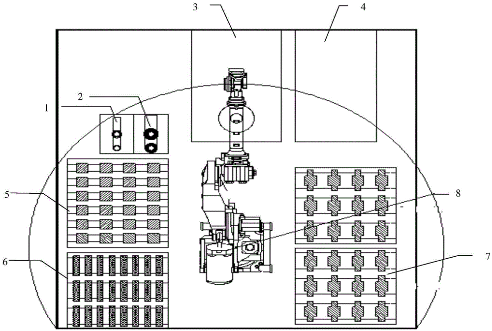
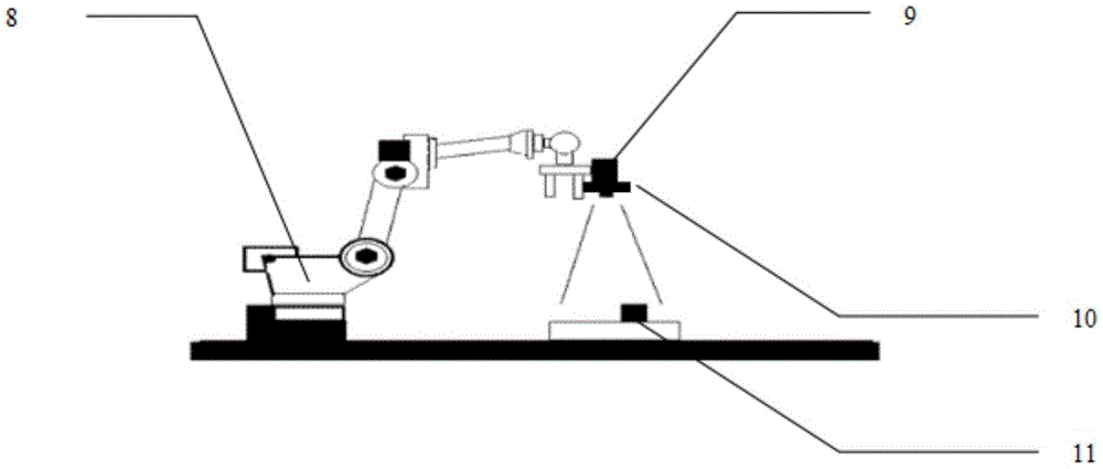
[0045] The motor rotor visual assembly production line in this embodiment includes shaft sleeve automatic discharge equipment 1, end plate automatic discharge equipment 2, single-arm hydraulic press 3, magnetic steel embedded equipment 4, rotor core tray 5, rotating shaft tray 6, and press-fit finished product tray 7 , robot 8, PLC (not shown in the figure), industrial camera 9, ring light source 10 and industrial tablet computer; wherein robot 8, PLC, single-arm hydraulic press 3, shaft sleeve automatic discharge equipment 1, rotor core tray 5, rotating shaft The pallet 6, the finished product pallet 7, the end plate automatic discharge equipment 2 and the magnetic steel equipment 4 form the robot execution system; the industrial camera 9, the ring light source 10 and the industrial tablet computer form the robot vision system;

[0046] The industrial camera 9 and the ring light source 10 are used to acquire images, and the industrial tablet computer is used to process the ima...


PUM


Abstract

The invention relates to a visual-assembly production line of a motor rotor and an assembly process. The visual-assembly production line is characterized by comprising shaft-sleeve automatic discharging equipment, end-plate automatic discharging equipment, a single-arm hydraulic machine, magnetic-steel embedding equipment, a rotor iron core pallet, a rotary-shaft pallet, a pressed-finished-product pallet, a robot, a PLC (Programmable Logic Controller), an industrial camera, a ring-shaped light source and an industrial flat-panel computer, wherein the robot, the PLC, the single-arm hydraulic machine, the shaft-sleeve automatic discharging equipment, the rotor iron core pallet, the rotary-shaft pallet, the pressed-finished-product pallet, the end-plate automatic discharging equipment and the magnetic-steel embedding equipment form a robot execution system; the industrial camera, the ring-shaped light source and the industrial flat-panel computer form a visual system of the robot; the industrial flat-panel computer is provided with visual software for recognizing the position of a workpiece; the ring-shaped light source is fixed on the industrial camera; and the industrial camera and the ring-shaped light source are coaxially arranged on a mechanical arm of the robot and are vertical to the surface of the workpiece when carrying out detection on the position of the workpiece.

Description

technical field [0001] The invention relates to the technical field of realizing the internal rotor assembly operation of electric vehicle motors, in particular to a motor rotor visual assembly production line and assembly process. Background technique [0002] The motor is an important device that converts electrical energy into mechanical energy. In the process of motor rotor assembly, the common solution is to realize production through manual operation combined with simple devices or simple semi-automation. However, in actual production, the motor rotor assembly process is complicated and cumbersome. Due to the processing and installation errors of the workpiece, it is difficult to meet high-precision automation. In order to solve these problems, there is an urgent need for a motor rotor visual assembly production line and assembly process. [0003] At present, within the scope of the applicant's search, although methods to solve existing problems have been proposed, fo...

Claims


Application Information

Patent Timeline
IPC IPC(8): H02K15/02
CPCH02K15/02
Inventor 陈海永王亚男张天江李泽楠曹军旗欧洋徐森
Owner HEBEI UNIV OF TECH
Why Eureka
Try Eureka