Optomechanical system for injecting light, optical coupler of said system, and illuminating device with said system

A mechanical system and optical coupling technology, applied in the direction of lighting devices, coupling of optical waveguides, light guides of lighting systems, etc., can solve the problems of complex design and manufacture, bulky emission system, etc., and achieve high-power applications and the best visual appearance Effect

Inactive Publication Date: 2016-06-08
SAINT GOBAIN ADFORS +1
View PDF11 Cites 1 Cited by
  • Summary
  • Abstract
  • Description
  • Claims
  • Application Information

AI Technical Summary

Problems solved by technology

[0010] the launch system described is still rather bulky and complex to design and manufacture

Method used


Image

  • Optomechanical system for injecting light, optical coupler of said system, and illuminating device with said system
  • Optomechanical system for injecting light, optical coupler of said system, and illuminating device with said system
  • Optomechanical system for injecting light, optical coupler of said system, and illuminating device with said system

Examples


Embodiment Construction

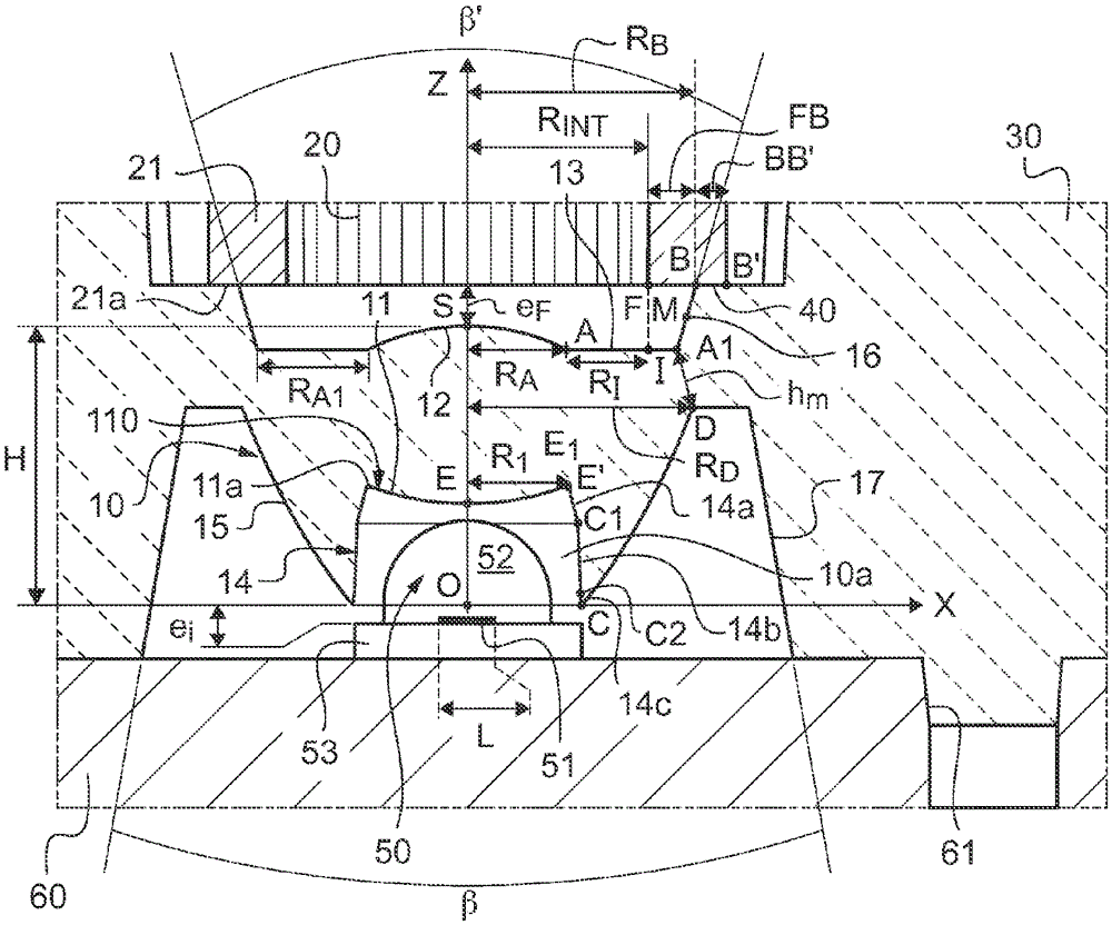
[0290] figure 2 (and image 3 , which is a detail view) shows a partial longitudinal cross-sectional view of an optomechanical system 1000 for a thin optical medium (preferably an emissive strip coupled to a light-emitting fabric) according to a first embodiment of the invention, said system comprising Optical coupler 1 comprising a transparent body obtained by molding made of PMMA (polymethyl methacrylate) with an optical refractive index n=1.5895 at 550 nm, said coupler being rotationally symmetric and having a central axis Oz, at One plane (O, X, Z) corresponding to the plane of the longitudinal section is shown and clearly defined, O being the center of the entrance of the optical coupler 1 .

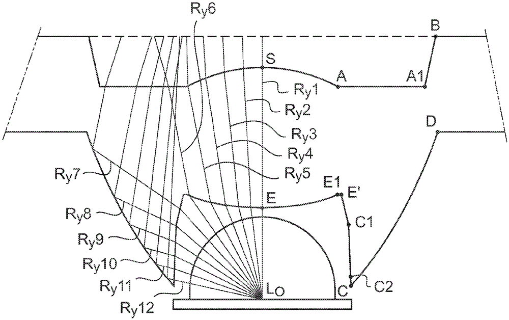
[0291] image 3 The traces of each surface of the optical coupler in the longitudinal section plane are shown and representative points are defined for each section, for clarity only in the positive quadrant of the section plane.

[0292] Optical coupler 1 consists of:

[0293] ...


PUM


Abstract

The invention relates to a system (1000) for injecting light, comprising: an optical coupler (1) having: a lens (10) having a convex entrance face (11) of radial extent R, a convex central exit face (12) and a peripheral exit face (13); a cavity (10a), containing the entrance face (11) and with an entrance lateral surface (14); and a peripheral reflective surface (15), encircling the lens and the cavity, extending beyond the entrance face (11); an optical collector (20), with an entrance, a collecting surface (20a) facing the central exit face, and a numerical aperture NA smaller than 1, the collector (20) comprising a jacket (21) having an end surface (21a); and a member (30) for aligning the optical collector (20), the optical coupler and the aligning member being integrally formed or being indirectly or directly fastened together, the central distance eF on the axis Oz between the collecting surface and the central exit face (12) being nonzero and smaller than 5 mm, and the system comprising a stop (40) for the end surface (21a). The invention also relates to the illuminating device with this system.

Description

technical field [0001] The invention relates to an optomechanical system for emitting light into an optical medium (light guide or extractor), an optical coupler of such a system and an illumination device with said system. [0002] More precisely, the invention relates to an optomechanical system for emitting light into a thin optical medium, the optical collector of which is formed by a bundle of optical fibers forming a thin light emitting strip, especially for emitting light into a thin light extraction medium, which is a light-emitting fabric including optical fibers. Background technique [0003] In the luminescent textile technology described, for example, in patent FR2859737, the illuminated surface is produced by the weaving of organic optical fibers with textile fibers. [0004] Patent application WO2007 / 003857A describes an optomechanical system of light emission, which relates to the field of display panels (advertising) illuminated by backlighting by means of o...

Claims


Application Information

Patent Timeline
Patent Type & Authority Applications(China)
IPC IPC(8): F21V5/04G02B6/42G02B19/00
CPCG02B6/0006G02B6/001G02B6/04G02B6/32G02B19/0028G02B19/0047
Inventor P.吉塞M.萨朗-福雷斯蒂C.布罗谢D.舍瓦利耶
Owner SAINT GOBAIN ADFORS
Why Eureka
Try Eureka