[0036] In order to be able to understand the above objectives, features and advantages of the present invention more clearly, the present invention will be further described in detail below in conjunction with the accompanying drawings and specific embodiments. It should be noted that the embodiments of the application and the features in the embodiments can be combined with each other if there is no conflict.
[0037] In the following description, many specific details are set forth in order to fully understand the present invention. However, the present invention can also be implemented in other ways different from those described here. Therefore, the protection scope of the present invention is not covered by the specific implementations disclosed below. Limitations of cases.
[0038] The electric pressure cooker according to some embodiments of the present invention will be described below with reference to the accompanying drawings.
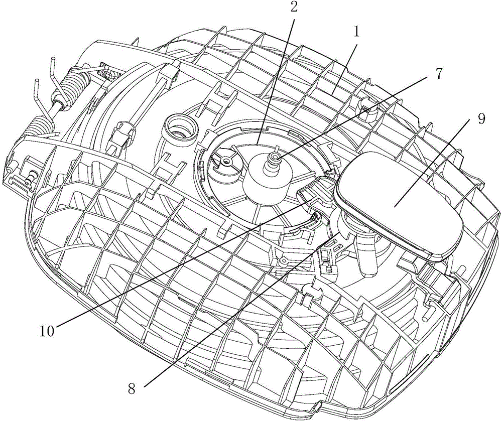
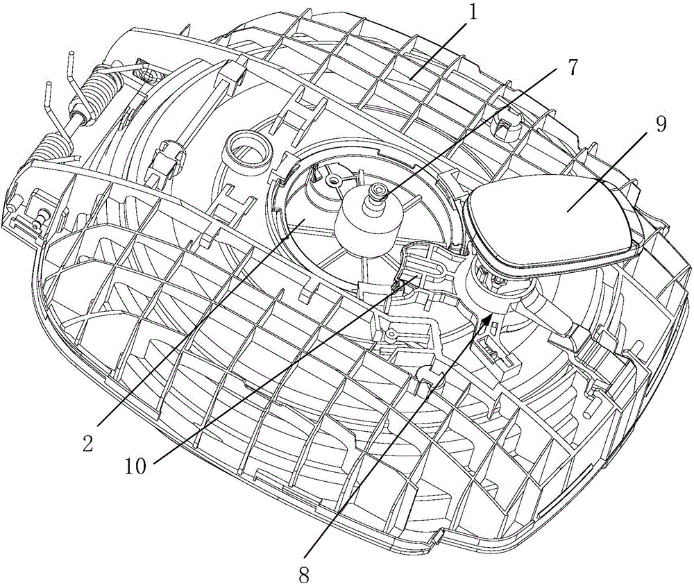
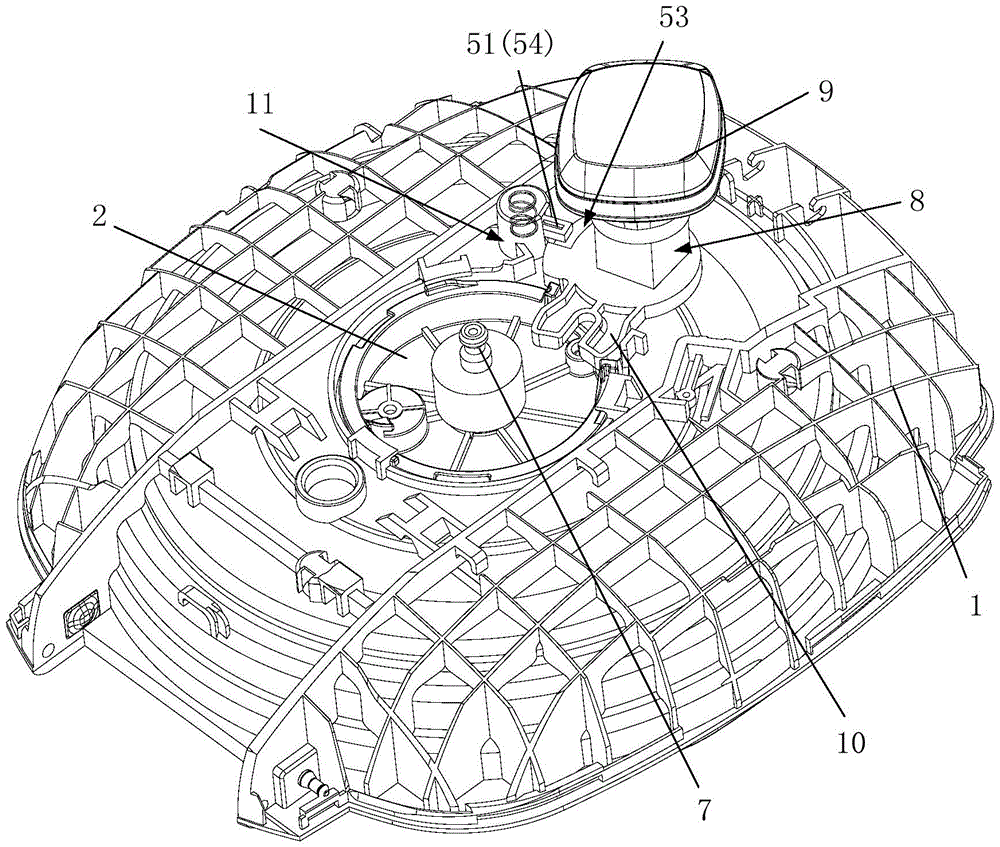
[0039] Such as Figure 1 to Figure 6 As shown, the present invention provides an electric pressure cooker, comprising: a pot body; an inner pot installed in the pot body; an inner cover 1 located above the pot body and rotatably connected to the pot body, In order to realize the opening or closing of the inner cover 1 on the pot body, wherein the middle part of the inner cover 1 has a mounting hole; a turntable 2 with a ring-shaped side wall and a bottom wall is mounted in the mounting hole and It can rotate around the axis of the mounting hole, and the lower end of the turntable 2 is matched with the pot cover 3 to realize that the pot cover 3 rotates with the turntable 2; the pot cover 3 is located in the inner cover 1 below and rotatably mounted on the inner cover 1; and a rotary hand assembly located above the inner cover 1 and rotatably mounted on the inner cover 1, and in the mounting hole Wherein: the rotating hand assembly and the turntable 2 have a matching rotation drive structure to realize the rotating hand assembly to drive the turntable 2 to rotate, the lower part of the rotating hand assembly has a matching part, the The side wall of the turntable 2 is provided with a matching opening correspondingly, and the outer end of the matching portion extends into the matching opening, and the two side walls of the matching part are matched with the two side walls of the matching opening to push the turntable 2 Rotate.
[0040] The electric pressure cooker provided by the present invention has a simple structure and is easy to assemble, which better improves the production efficiency of the electric pressure cooker; moreover, the rotary handle assembly is located in the middle of the lid 3 and is eccentrically arranged, and the user only needs to make the rotary handle assembly rotate less. The action of opening and closing the lid 3 can be completed at an angle, and its operability is more obvious, and there is no driving dead angle, and its use performance is better. Wherein, the fork pulls the rotation of the turntable by matching the side wall of the matching portion with the side wall of the matching opening. Specifically, the two sides of the mating part respectively have driving surfaces that cooperate with the two side walls of the mating opening, so that one side of the mating part cooperates with a side wall of the mating opening during the opening process to drive the turntable to rotate , In the process of closing the cover, the other side of the matching part is matched with the other side wall of the matching opening to drive the turntable to rotate in the reverse direction. The driving mode of the matching part side wall and the matching opening is adopted, which makes the driving structure between the turntable and the rotary hand simple. The side wall of the linkage slider is used as the drive, because the linkage slider has a certain width, high strength and wear resistance The drive structure is more reliable; the turntable is provided with a matching port as the drive structure, and the two side walls of the matching port are used as the drive surface, which has high wear resistance and makes the transmission more reliable; and the drive structure makes full use of the rotation between the hand and the turntable. The turning hand only needs to rotate a small angle to open and close the lid.
[0041] According to an embodiment of the present invention, the rotation angle of the turntable is 25°-45°, and the rotation angle of the rotating hand assembly is 30°-90°; preferably, the rotation angle of the rotating hand assembly is 30° ~60°. Compared with the prior art, the lid can be opened and closed only when the rotary hand rotates more than 100°, and the lid can be opened and closed only by rotating the rotary hand at a smaller angle.
[0042] Wherein, the pot cover 3 is also provided with a sealing ring.
[0043] In addition, the electric pressure cooker according to the foregoing embodiment of the present invention has the following additional technical features:
[0044] In an embodiment of the present invention, such as image 3 with Figure 4 As shown, the electric pressure cooker further includes: a lock catch 4, the inner cover 1 is also provided with an accommodating hole 11, the accommodating hole 11 is located on the side of the hand assembly, the lock catch 4 is installed in the In the receiving hole 11, and its lower end is supported on the pot cover 3; where: Figure 7 with Figure 8 As shown, the upper end of the lock buckle 4 and the turntable 2 have a mating locking structure to realize the locking of the rotary handle assembly when the pot cover 3 is removed (that is, the rotation of the rotary handle assembly is restricted , So that it no longer has the function of turning), and after installing the pot cover 3, unlock the hand assembly (that is, release the restriction on the hand assembly to make it have the function of rotation).
[0045] In this way, when the lid 3 is removed and the screw handle assembly is taken, the inner lid can be held stably, which has better operability and is more convenient for users to operate; at the same time, it can also avoid the occurrence of the lid 3 being installed without the lid 3 The cooking problem (that is, the user cannot close the lid without installing the lid 3, and the rotary hand assembly cannot rotate), which effectively improves the safety of use.
[0046] Specifically, such as image 3 with Figure 4 As shown, the locking structure includes a locking tongue 51 and a locking groove 52, one of the locking tongue 51 and the locking groove 52 is located on the lock buckle 4, and the other is located on the rotary handle assembly .
[0047] Can be: such as image 3 with Figure 4 As shown, the lock tongue 51 is located on the lock buckle 4, and the locking groove 52 is located on the rotating hand assembly; wherein: the locking groove 52 is an opening facing the lock buckle 4 and passing through above The lock tongue 51 can move down into the groove or move up to above the groove.
[0048] Wherein, the accommodating hole 11 is a blind hole structure with an opening facing downward and a hole wall protruding upward from the upper surface of the inner cover 1, and the side wall of the accommodating hole 11 facing the side of the hand screw assembly has a longitudinal arrangement The guide groove 53 of the lock catch 4 has a guide rib 54 on the side wall, the guide rib 54 is located in the guide groove 53, and the lock catch 4 is extended by the guide rib 54 The outer end of the groove 53 can be locked with the rotating hand assembly, that is, the locking tongue 51 is located on the end of the guide rib protruding out of the guide groove 53.
[0049] It may also be that the locking tongue 51 is located on the rotating hand assembly, and the locking groove 52 is located on the lock catch 4; wherein: the locking groove 52 has an opening facing downward and facing the rotating hand A through groove on the component side, the locking groove 52 can move down to accommodate the lock tongue 51, or move up to above the lock tongue 51 (not shown in this scheme).
[0050] Wherein, the accommodating hole 11 is a blind hole structure with an opening facing downward and a hole wall protruding upward from the upper surface of the inner cover 1, and the side wall of the accommodating hole 11 facing the side of the hand screw assembly has a longitudinal arrangement The guide groove 53 of the lock catch 4 has a guide rib 54 on the side wall, the guide rib 54 is located in the guide groove 53, and the lock catch 4 is extended by the guide rib 54 The outer end of the groove 53 is used to lock the hand assembly, that is, the condensing groove 53 is located on the end of the guide rib protruding outside the guide groove 53.
[0051] The above two schemes can achieve the purpose of this application, and their purpose does not deviate from the design idea of the present invention, which will not be repeated here, but should fall within the protection scope of this application.
[0052] Further, as image 3 with Figure 4 As shown, the electric pressure cooker further includes: an elastic member 6 located in the receiving hole 11 and supported between the upper end surface of the lock catch 4 and the bottom wall of the receiving hole 11.
[0053] The upper end of the lock catch 4 is pressed tightly by an elastic member, so that the lock catch 4 is pushed to move downward after the pot cover 3 is removed, so that the lock tongue 51 and the lock groove 52 are quickly matched.
[0054] Of course, the lock buckle 4 can also be moved down under the action of gravity to realize the rapid coordination of the lock tongue 51 and the locking groove 52, which can also achieve the purpose of this application. Its purpose does not deviate from the design idea of the present invention and should belong to this application. Within the scope of protection.
[0055] Preferably, the elastic member 6 is a coil spring.
[0056] Further, such as Figure 1 to Figure 6 , Picture 9 As shown, the electric pressure cooker further includes: a pivot 7 whose lower end is connected to the pot cover 3 and an upper end of which is connected to the turntable 2; and one of the turntable 2 and the pot cover 3 has The plug tongue and the other has a first slot, and the plug tongue is inserted into the first slot to position the turntable 2 and the pot cover 3 to realize the turntable 2 and the pot The cover 3 rotates simultaneously.
[0057] In an embodiment of the present invention, such as Figure 1 to Figure 6 As shown, the rotary hand assembly includes: a fork 8 located above the inner cover 1 and rotatably mounted on the inner cover 1 and matched with the turntable 2; and a rotary hand 9, It is located above the fork 8 and installed on the fork 8 (installed on the fork body of the fork 8), and is used to drive the fork 8 to rotate.
[0058] Preferably, such as Figure 1 to Figure 6 As shown, the fork 8 has a drive arm 10 (the inner end of the drive arm 10 is connected to the fork body of the fork 8), the side wall of the turntable 2 has a matching opening, and the drive arm 10 is inserted It is installed in the matching port and is used to turn the turntable 2 to rotate.
[0059] Wherein, the fork 8 pushes the turntable 2 to rotate by matching the side wall of the driving arm 10 with the side wall of the matching opening.
[0060] In this application, the turntable is only provided with a matching port, which makes the turntable easy to form (less material is used to save costs, and the mold speed is fast to improve production efficiency), and the matching port is not easy to wear (even if there is slight wear, it will not affect the turntable Strength); The driving arm 10 of the fork 8 has a high structural strength.
[0061] This solution has a simple structure, convenient assembly, and good performance stability (on the one hand, the fork 8 has high strength, on the other hand, the matching mouth of the turntable has strong resistance to deformation), and its practicability is more significant.
[0062] Moreover, the outer ends of the two side walls of the driving arm 10 both have a first curved surface 12, and the middle part has a second curved surface 13. The first curved surface 12 and the second curved surface 13 are smoothly transitioned and connected, and the driving arm 10 The first curved surface 12 and the second curved surface 13 are matched with the two side walls of the mating opening, so that the driving arm 10 and the turntable 2 are smoothly transmitted during the mating process, avoiding the one-way transmission process There are vacancies to better ensure the reliability of the transmission.
[0063] Further, the first curved surface 12 and the second curved surface 13 form a cylindrical convex curved surface on the side wall of the driving arm 10, and the peak line 14 of the convex curved surface is located on the first curved surface 12 At the transitional junction with the second curved surface 13; wherein, during the reciprocating rotation of the turntable 2, the two side walls of the mating port always correspond to the two convex curved surfaces.
[0064] By designing the arcs of the two side walls of the driving arm 10, it is always in contact with the two side walls of the mating opening during the reciprocating rotation, which can eliminate the vacancies that exist during the reverse rotation and enable continuous reciprocating rotation. , It is more convenient for users to operate, and can improve the user experience.
[0065] In summary, the electric pressure cooker provided by the present invention has a simple structure and is easy to assemble, which better improves the production efficiency of the electric pressure cooker; moreover, the rotary hand assembly is located in the middle of the lid and is eccentrically arranged, and the user only needs to use the rotary hand assembly Turning a small angle can complete the action of opening and closing the lid, its operability is more obvious, and there is no driving dead angle, and its use performance is better.
[0066] In the description of the present invention, the terms "installed", "connected", "connected", "fixed", etc. should be understood in a broad sense. For example, "connected" may be a fixed connection, a detachable connection, or an integral Connection; it can be directly connected or indirectly connected through an intermediary. For those of ordinary skill in the art, the specific meanings of the above terms in the present invention can be understood according to specific circumstances.
[0067] In the description of this specification, the description of the terms "one embodiment", "some embodiments", "specific embodiments", etc. means that specific features, structures, materials or characteristics described in conjunction with the embodiment or examples are included in the present invention In at least one embodiment or example. In this specification, the schematic representation of the above-mentioned terms does not necessarily refer to the same embodiment or example. Moreover, the described specific features, structures, materials or characteristics may be combined in any one or more embodiments or examples in a suitable manner.
[0068] The above are only preferred embodiments of the present invention and are not used to limit the present invention. For those skilled in the art, the present invention can have various modifications and changes. Any modification, equivalent replacement, improvement, etc., made within the spirit and principle of the present invention shall be included in the protection scope of the present invention.