Water film pipe deduster

A dust collector and water film technology, applied in chemical instruments and methods, use of liquid separation agents, combined devices, etc., can solve problems affecting the life and work of surrounding and staff, discount of dust removal effect, dust filtration, and adsorption capacity of wet dust collectors Limited and other problems, to achieve the effect of improving the dust removal effect, improving the dust removal effect, and improving the contact time

Active Publication Date: 2016-06-15
广西钦州恒星锰业有限责任公司
View PDF3 Cites 0 Cited by
  • Summary
  • Abstract
  • Description
  • Claims
  • Application Information

AI Technical Summary

Problems solved by technology

[0002] The wet dust collector is commonly known as "water dust collector". It makes the dusty gas and the liquid come into close contact, and uses the inertial collision of water droplets and particles or the full mixing of water and dust and other functions to trap particles or increase the size of the particles or leave them behind. A device that achieves the separation effect of water and dust in a fixed container; the current commonly used wet dust collector directly passes the dust-containing gas into the water chamber, and the air bubbles and water film are generated in the water body through the air flow, thereby realizing dust removal; this dust removal method will produce Loud noise affects the normal life and work of the surrounding and staff; as the gas is directly passed into the purified water, the dust in the gas directly pollutes the entire purification tank, so in each water change cycle, only the first half cycle can efficiently remove dust, and then With the extension of the use time of purified water, the dust removal effect will be significantly reduced; in addition, the gas in the traditional dust collector and the purified water only contact for a short time to form a water film, so the purified water has limited ability to filter and absorb dust in the gas. This makes the dust removal effect of the wet dust collector greatly reduced

Method used


Image

  • Water film pipe deduster
  • Water film pipe deduster
  • Water film pipe deduster

Examples


Embodiment

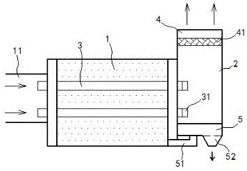
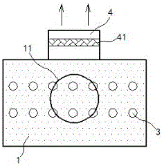
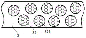
[0013] exist Figure 1 to Figure 3 In the shown embodiment, the water film tube dust collector includes a dust removal chamber 1 and a separation chamber 2, and the separation chamber 2 is placed on the right side of the dust removal chamber 1; the dust removal chamber 1 is filled with purified water, and the dust removal chamber 1 is filled with purified water. A viscous agent is added to the purified water; water film tubes 3 are arranged parallel and equidistant in the dust removal chamber 1, and the water film tubes 3 are made of hard materials. Water inlet holes 32 are provided equidistantly on the top; silk screens 321 are fixed at each of the water inlet holes 32; each of the water film tubes 3 horizontally runs through the left and right side walls of the dust removal chamber 1; The left end communicates with the intake pipe 11, and the right end of the water film pipe 3 stretches into the separation chamber 2, and a shut-off valve 31 is also installed on the right end...


PUM


Abstract

The invention relates to a water film pipe deduster. The water film pipe deduster comprises a dedusting cavity and a separation cavity. The dedusting cavity is filled with purified water, water film pipes made of a hard material are parallelly arranged in the dedusting cavity at an equal space, and water inlet holes are disposed on the water film pipe walls at an equal space. All the water film pipes run through the left and right side walls of the dedusting cavity horizontally. The left ends of the water film pipes are communicated with an air inlet pipe, the right ends of the water film pipes stretch into the separation cavity, and the right ends of the water film pipes are also equipped with stop valves. The top of the separation cavity is equipped with an exhaust port, where a dryer is mounted. The bottom of the separation cavity is equipped with a separator for filtering dust and water. The separator includes a return pipe and a sewage drain port, and the return pipe is communicated with the dedusting cavity. The deduster has a novel principle, can effectively improve the dedusting effect, has small dedusting noise, and also can effectively improve the utilization rate of purified water.

Description

technical field [0001] The invention relates to a dust collector, especially a wet dust collector. Background technique [0002] The wet dust collector is commonly known as "water dust collector". It makes the dusty gas and the liquid come into close contact, and uses the inertial collision of water droplets and particles or the full mixing of water and dust and other functions to trap particles or increase the size of the particles or leave them behind. A device that achieves the separation effect of water and dust in a fixed container; the current commonly used wet dust collector directly passes the dust-containing gas into the water chamber, and the air bubbles and water film are generated in the water body through the air flow, thereby realizing dust removal; this dust removal method will produce Loud noise affects the normal life and work of the surrounding and staff; as the gas is directly passed into the purified water, the dust in the gas directly pollutes the enti...

Claims


Application Information

Patent Timeline
Patent Type & Authority Applications(China)
IPC IPC(8): B01D47/00B01D50/00B01D53/26
CPCB01D47/00B01D53/26B01D50/10
Inventor 王富强
Owner 广西钦州恒星锰业有限责任公司
Why Eureka
Try Eureka