Punching and flanging machine

A flanging machine and punching technology, which is applied in the field of punching and flanging machines, can solve problems such as low processing efficiency, complex molds, and easy wear of the cutter head, and achieve the effect of reducing labor intensity and low replacement cost

Active Publication Date: 2016-06-15
王向阳 +1
View PDF12 Cites 18 Cited by
  • Summary
  • Abstract
  • Description
  • Claims
  • Application Information

AI Technical Summary

Problems solved by technology

[0002] At present, the methods for drilling holes on the surface of the pipe and flanging the holes are as follows: 1. A kind of processing equipment for flanging the pipe hole in the Chinese invention patent (notification number CN2905260Y) discloses that the processing equipment can turn the pipe hole Edge method: limit the pipe material in the fixed frame formwork, position the flanging punch on the bottom plate of the supporting form, penetrate the bottom plate of the supporting form into the pipe with the drilled hole, and lift the bottom plate of the supporting form upwards. Insert the top of the flanging punch into the hole of the pipe, fix the demoulding bottom plate, press the die plate on the pipe, connect the bottom end of the tie rod with the flanging punch, and then use the stretching equipment Pull the pull rod until the pull rod completely pulls the flanging punch out of the hole of the pipe. The mold used in this method is complicated and the processing steps are cumbersome. Every time the punch is put into the pipe through the demoulding base plate, and then To penetrate the hole, it is necessary to carry out a step of connecting and fixing with the stretching equipment, the processing efficiency is low, and there is no value for mass production; Use a drill to process a round hole, then repair the round hole into an oval hole, replace the drill with a drill with a protruding part, then put the drill with a protruding part into the hole, pull it up while rotating, and process it into a flanging After flanging, use an edge grinding tool to grind it flat. This processing method has high requirements on the rigidity of the cutter head, and the cutter head is easy to wear. The flanged hole after processing needs to be polished. For thin-walled pipe fittings, it is helpless for pipe fittings with high hardness such as thick-walled pipe fittings, long pipe fittings and stainless steel pipes.

Method used


Image

  • Punching and flanging machine
  • Punching and flanging machine
  • Punching and flanging machine

Examples


Embodiment 1

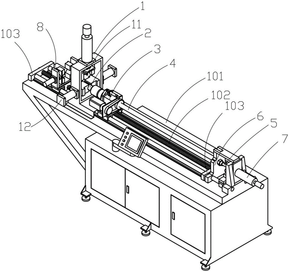
[0039] Embodiment 1: refer again Figure 8 , the above-mentioned groove 241 is arranged along the length direction of the above-mentioned frame 101 to be low at the front and high at the back. When this embodiment is working: the pipe fittings are fed in from the 8 ends of the front feeding cart, the pipe fittings are inserted into the mold core 2, and pass through the punching mechanism 1 to the rear positioning block of the rear feeding cart 3, and the rear feeding cart 3 clamps the pipe fittings and goes Pull the rear end of the frame 101 until the rear feeding vehicle 3 reaches the end of the above-mentioned frame 101, the front feeding vehicle 8 clamps the pipe fittings, the rear feeding vehicle 3 releases the pipe fittings and moves to the front end of the above-mentioned frame 101, and the rear feeding vehicle 3 clamps For pipe fittings, the front feeding truck 8 releases the pipe fittings, and the rear feeding truck 3 pulls the pipe fittings toward the rear end of the ...

Embodiment 2

[0040] Embodiment 2: Refer again Figure 9 , the above-mentioned groove 241 is arranged along the length direction of the above-mentioned frame 101 with the front high and the rear low. Harder pipe fittings, with the mode of pulling, taper tongue rod connecting rod 5 is difficult for deformation. When this embodiment is working: the pipe fittings are fed in from the 8 ends of the front feeding cart, the pipe fittings are inserted into the mold core 2, and pass through the punching mechanism 1 to the rear positioning block of the rear feeding cart 3, and the rear feeding cart 3 clamps the pipe fittings and goes Pull the rear end of the frame 101 until the rear feeding vehicle 3 reaches the end of the above-mentioned frame 101, the front feeding vehicle 8 clamps the pipe fittings, the rear feeding vehicle 3 releases the pipe fittings and moves to the front end of the above-mentioned frame 101, and the rear feeding vehicle 3 clamps For pipe fittings, the front feeding truck 8 re...


PUM


Abstract

The invention provides a punching and flanging machine. The punching and flanging machine comprises a rack and a punching mechanism and a front feeding car which are arranged on the rack. The punching and flanging machine is characterized in that the working end of the punching mechanism is provided with a punching pin of which the cross section is in an elliptic shape, and the rack is further sequentially provided with outer mold clamping blocks, a mold core, a back feeding car, a hollow mold core connecting rod, a cone tongue rod connecting rod, a mold core connecting rod fixing seat and a flanging drive oil cylinder; the mold core comprises a hollow outer mold core body, a mold core insert inserted into the top of the outer mold core body, a flanging punch and a cone tongue rod, wherein the flanging punch and the cone tongue rod are arranged in an inner cavity of the outer mold core body, the flanging punch is arranged on the cone tongue rod in a sleeving mode, the cone tongue rod is connected to the flanging drive oil cylinder through the cone tongue rod connecting rod, and the cone tongue rod is moved to push the flanging punch to perform hole flanging machining. The punching and flanging machine is few in process, high in hole flanging efficiency, little in mold wear, durable, low in machining cost and capable of machining thin-wall and thick-wall pipes and machining a same pipe fitting in the different directions.

Description

technical field [0001] The invention relates to the field of drilling and flanging, in particular to a punching and flanging machine. Background technique [0002] At present, the methods for drilling holes on the surface of the pipe and flanging the holes are as follows: 1. A kind of processing equipment for flanging the pipe hole in the Chinese invention patent (notification number CN2905260Y) discloses that the processing equipment can turn the pipe hole Edge method: limit the pipe material in the fixed frame formwork, position the flanging punch on the bottom plate of the supporting form, penetrate the bottom plate of the supporting form into the pipe with the drilled hole, and lift the bottom plate of the supporting form upwards. Insert the top of the flanging punch into the hole of the pipe, fix the demoulding bottom plate, press the die plate on the pipe, connect the bottom end of the tie rod with the flanging punch, and then use the stretching equipment Pull the pul...

Claims


Application Information

Patent Timeline
Patent Type & Authority Applications(China)
IPC IPC(8): B21D35/00B21D28/28B21D19/08
CPCB21D19/088B21D28/28B21D35/002
Inventor 王向阳吴胜利吴峰峰吴明明王曙光王志华
Owner 王向阳
Why Eureka
Try Eureka