A nail feeding device for automatic drilling and riveting machine

An automatic drilling riveting machine and nail feeding technology, which is applied in the field of aviation manufacturing, can solve problems such as unfavorable production efficiency, large nail feeding structure, and complicated nail feeding process, and achieve the effect of compact structure and guaranteed clamping effect

Active Publication Date: 2017-10-31
ZHEJIANG UNIV
View PDF1 Cites 0 Cited by
  • Summary
  • Abstract
  • Description
  • Claims
  • Application Information

AI Technical Summary

Problems solved by technology

The nail feeding process in this technical solution is complicated, and the nail feeding structure is huge, which is not conducive to improving production efficiency

Method used


Image

  • A nail feeding device for automatic drilling and riveting machine
  • A nail feeding device for automatic drilling and riveting machine
  • A nail feeding device for automatic drilling and riveting machine

Examples


Embodiment Construction

[0033] The specific embodiments of the present invention will be described below in conjunction with the accompanying drawings.

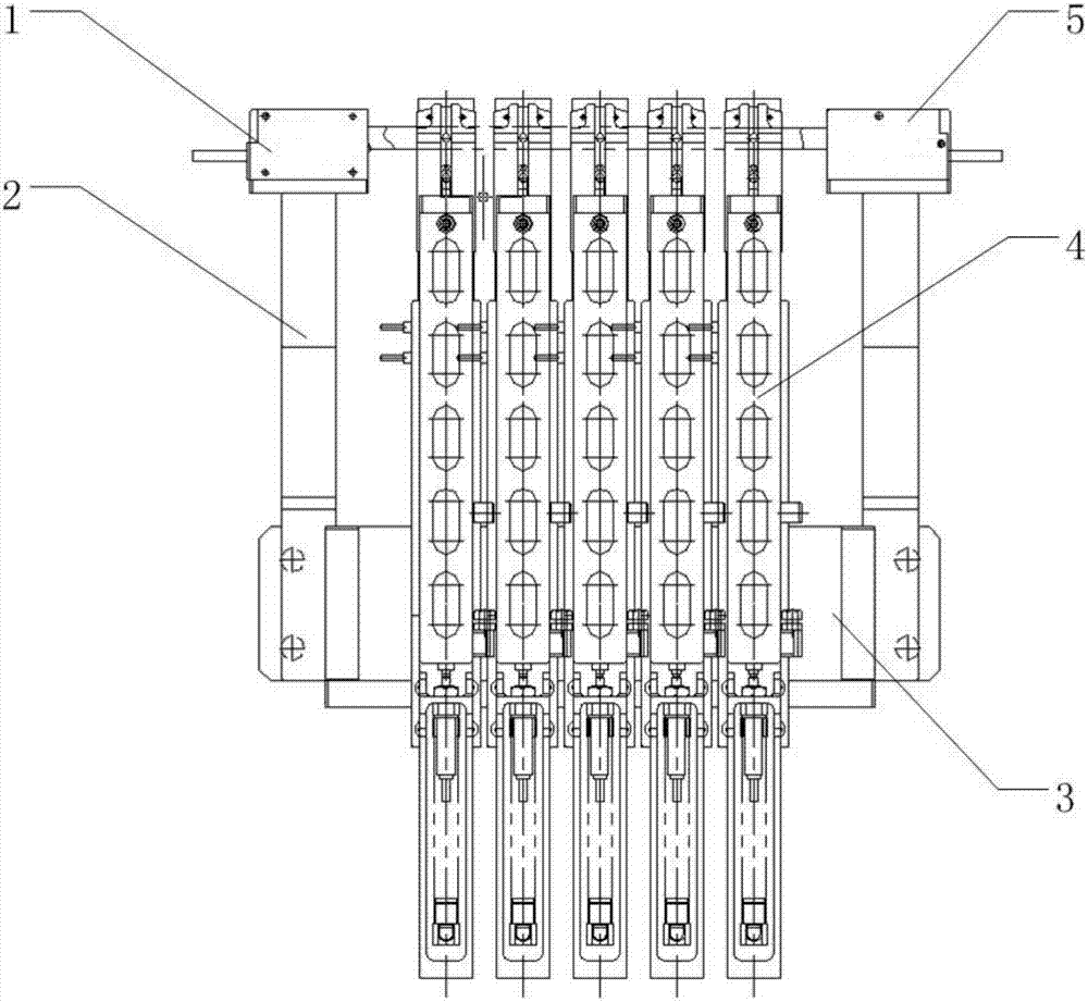
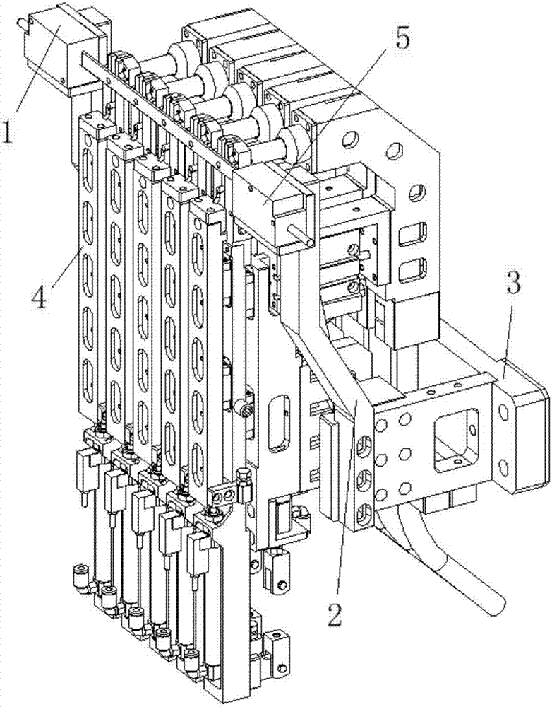
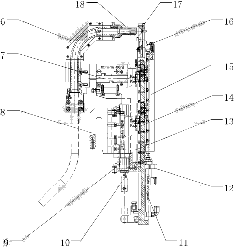
[0034] Such as Figure 1 to Figure 5 As shown, a nail feeding device for an automatic drilling and riveting machine is characterized in that it includes a base 3, a delivery elbow 6, a nail output cylinder 7, a fork-shaped mounting seat 8, a first telescopic cylinder 9, a cylinder bracket 10, a first telescopic layer 11. Second telescopic cylinder 12, base rail seat 13, miniature linear guide rail 14, second telescopic layer 15, push nail head 16, nail output head 18, laser micrometer launcher 1, sensor bracket 2, laser micrometer The receiving end 5 , the cover plate 19 , the nail base plate 20 , the first nail auxiliary claw 21 , the first spring seat 22 , the second nail nail auxiliary claw 23 , the spring 24 , and the second spring seat 25 . Wherein, the second telescopic layer 15 is connected to the first telescopic layer 11 through the guide ...


PUM


Abstract

The invention discloses a rivet feeding device of an automatic drill-riveting machine. The rivet feeding device of the automatic drill-riveting machine comprises a base, a rivet output module mounted on the base in a sliding manner, a rivet clamping module for bearing and clamping rivets, a detecting module for detecting the size of the rivets, and a nail feeding module for conveying the rivets from the rivet clamping module to a lower computer. The rivet output module comprises a rivet output head with a conveying elbow and a rivet output driving device for driving the rivet output module to slide. The rivet clamping module comprises a rivet clamping base plate mounted on the base and a rivet clamping claw hinged to the rivet clamping base plate and matched with the rivet output head. The rivet feeding module comprises a telescopic assembly mounted on the base in a sliding manner, a rivet push head fixed to the top of the telescopic assembly and used for opening the rivet clamping claw to conveying out the rivets, and a telescopic driving device for driving the telescopic assembly to slide. The rivet feeding device has the beneficial effects of being compact in structure, reliable, efficient, economical and environment-friendly.

Description

technical field [0001] The invention relates to the field of aviation manufacturing, in particular to a nail feeding device for an automatic drilling and riveting machine. Background technique [0002] In the assembly of metal components such as aircraft panels, riveting is still one of the most important connection methods at present, occupying a huge workload. Traditional manual riveting has poor working conditions and low production efficiency. The quality of riveting depends heavily on the experience and technology of workers, and does not meet the development requirements of aircraft digital assembly. Therefore, it is imperative to use automatic drilling and riveting machines to replace manual operations. However, the principle and structure of high-end automatic drilling and riveting machines are quite complicated. At present, only a few manufacturers in Europe and the United States have the ability to develop and manufacture, such as EI, GEMCOR, BROETJE, etc. The deve...

Claims


Application Information

Patent Timeline
Patent Type & Authority Patents(China)
IPC IPC(8): B21J15/32
CPCB21J15/32
Inventor 柯映林蒋君侠柯臻铮董辉跃李江雄黄浦缙
Owner ZHEJIANG UNIV
Why Eureka
Try Eureka