
Rotating fixture and rotating welding device

A technology of rotating fixture and rotating drive device, applied in auxiliary devices, welding equipment, welding equipment, etc., can solve the problems of inconvenient operation and complicated fixture

Active Publication Date: 2016-06-15
HANS LASER TECH IND GRP CO LTD
View PDF6 Cites 17 Cited by
  • Summary
  • Abstract
  • Description
  • Claims
  • Application Information

AI Technical Summary

Problems solved by technology

[0004] The purpose of the embodiments of the present invention is to provide a rotary fixture and a rotary welding device to solve the problems of complicated and inconvenient operation of the existing fixtures

Method used


Image

  • Rotating fixture and rotating welding device
  • Rotating fixture and rotating welding device
  • Rotating fixture and rotating welding device

Examples


Embodiment Construction

[0023] In order to make the object, technical solution and advantages of the present invention clearer, the present invention will be further described in detail below in conjunction with the accompanying drawings and embodiments. It should be understood that the specific embodiments described here are only used to explain the present invention, not to limit the present invention.

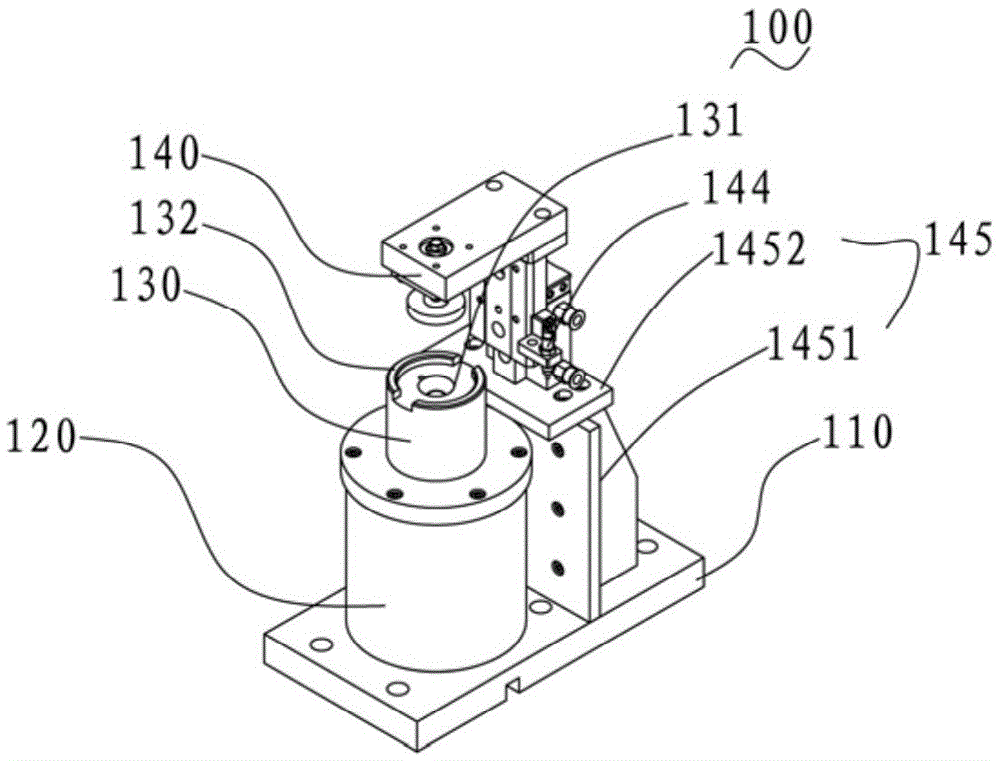
[0024] Such as image 3 As shown, the embodiment of the present invention provides a rotary fixture 100 on which a product to be welded (not shown) is fixed, and the rotary fixture 100 includes a base 110 as a base, a The rotary drive device 120, the positioning device 130 for positioning the product to be welded, and the pressing device 140 that cooperates with the positioning device 130 to compress the product to be welded; wherein, the pressing The device 140 is provided with a rotatable pressure head 141, and the positioning device 130 is fixed on the rotating end (not shown) of the rotary dri...


PUM


Abstract

The invention is suitable for the field of laser machining, and provides a rotating fixture. The rotating fixture comprises a base, a rotating driving device, a positioning device and a pressing device, wherein the base is used as a substrate; the rotating driving device is positioned on the base; the positioning device is used for positioning a product to be welded; the pressing device is matched with the positioning device to press the product to be welded; a rotatable pressing head is arranged on the pressing device; the positioning device is fixed at a rotating end of the rotating driving device; and the rotating driving device drives the positioning device, the product to be welded and the pressing head to rotate integrally. According to an embodiment, the product to be welded rotates but a welding head is fixed, so that complexity of the mechanism is reduced, shaking during rotating of the fixture, and unsmooth welding, product air leakage and the like which are caused by shaking are reduced to a maximum extent; the rotating fixture is prevented from interfering with a laser beam and the welding head; and by pneumatic clamping and discharging of a cylinder, efficient and automatic welding is realized. The embodiment of the invention further provides a rotating welding device.

Description

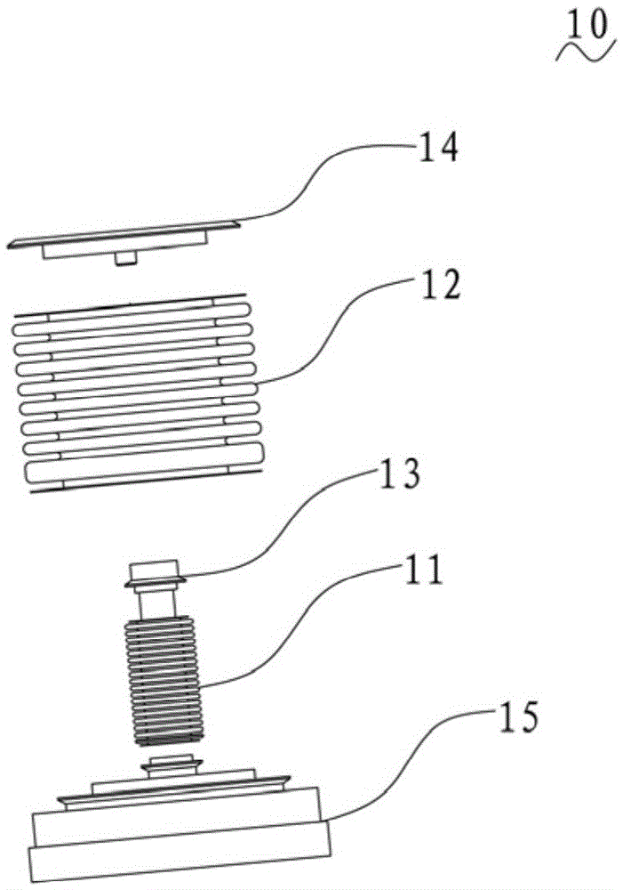
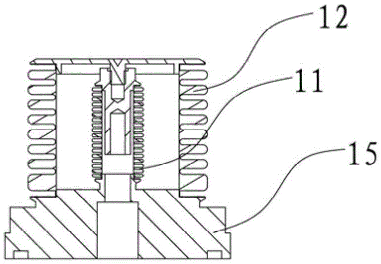
technical field [0001] The invention belongs to the field of laser welding, in particular to a rotary fixture and a rotary welding device using the rotary fixture. Background technique [0002] With the demand of the market, welding products are increasingly diversified, such as straight cylinders, trapezoidal cylinders, polygons and other special-shaped bodies, which need to be welded by rotation. Due to the irregularity of the products, not only the positioning accuracy is low during the welding process, Moreover, a specific jig is required to achieve positioning. Once the welding object is changed, the jig also needs to be replaced, which makes the processing cost high and the operation is inconvenient. [0003] For example, when welding electric bellows in the application field, tungsten inert gas shielded welding, micro-beam plasma welding, electric beam welding, etc. currently used in the market have high requirements for operators. Such as figure 1 , 2 As shown, th...

Claims


Application Information

Patent Timeline
Patent Type & Authority Applications(China)
IPC IPC(8): B23K37/047B23K37/053B23K26/282B23K101/36
CPCB23K26/282B23K37/047B23K37/053B23K2101/36
Inventor 李东飞高云峰
Owner HANS LASER TECH IND GRP CO LTD
Learn More