Under-actuated mechanical arm wrist based on gear transmission

A gear transmission and under-actuation technology, which is applied in the direction of manipulators, manufacturing tools, joints, etc., can solve the problems that the manipulator does not have multiple power outputs and cannot meet the environmental requirements of nuclear power plants, so as to avoid mutual interference and facilitate centralized protection and work The effect of high reliability

Active Publication Date: 2016-06-15
HARBIN INST OF TECH
View PDF8 Cites 0 Cited by
  • Summary
  • Abstract
  • Description
  • Claims
  • Application Information

AI Technical Summary

Problems solved by technology

[0003] The purpose of the present invention is to solve the problem that the existing various mechanical arm wrists cannot meet the environmental requirements of nuclear power plants because the mechanical arm does not have multiple power output functions

Method used


Image

  • Under-actuated mechanical arm wrist based on gear transmission
  • Under-actuated mechanical arm wrist based on gear transmission
  • Under-actuated mechanical arm wrist based on gear transmission

Examples


specific Embodiment approach 1

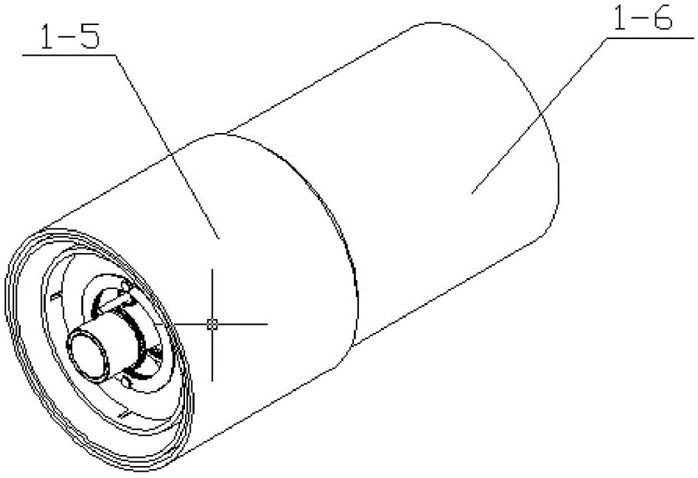
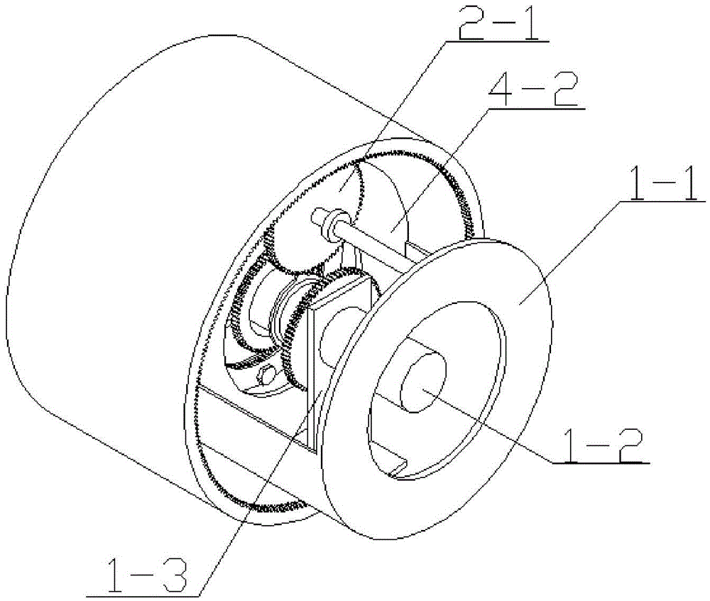
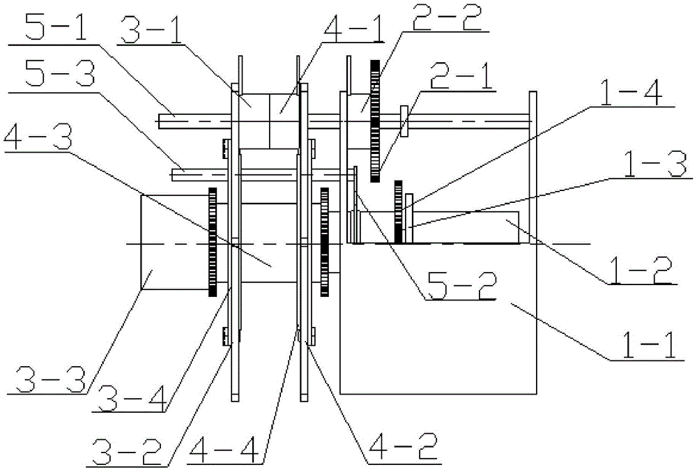
[0015] Specific implementation mode one: combine Figure 1-Figure 6 To illustrate this embodiment, an underactuated mechanical arm wrist based on gear transmission in this embodiment includes a wrist body and a mechanical structure shell 1-5, the mechanical structure shell 1-5 is set on the wrist body, and the wrist body includes a fixed end 1-5 1. Motor 1-2, motor support 1-3, input gear end 1-4, support shaft 5-1, outer layer transmission gear 2-1, outer layer clutch 2-2, shaft passing rod 5-2, Wheel shaft 5-3, inner wheel 3-5, middle wheel 4-5, two-way clutch left end 3-1, two inner baffles 3-4, inner ring gear 3-2, inner output End 3-3, two-way clutch right end 4-1, middle-level ring gear 4-2, middle-level output end 4-3 and two middle-level baffle plates 4-4,

[0016] The motor support 1-3 is fixedly installed on the fixed end 1-1, the motor 1-2 is installed on the motor support 1-3, the support shaft 5-1 is parallel to the output end of the motor 1-2 and fixedly install...

specific Embodiment approach 2

[0019] Specific implementation mode two: combination Image 6 Describe this embodiment, the fixed end 1-1 of this embodiment includes a first ring body 1-1-1, a second ring body 1-1-2 and a connecting body 1-1-3, the first ring body 1-1 -1 and the second annular body 1-1-2 are arranged side by side, and the outer edge of the first annular body 1-1-1 and the outer edge of the second annular body 1-1-2 pass through the connecting body 1-1- 3 connections. With such a setting, the movement is more flexible. Other compositions and connections are the same as in the first embodiment.

specific Embodiment approach 3

[0020] Specific implementation mode three: combination Figure 2-Figure 3 Describe this embodiment, the mechanical structure housing 1-5 of this embodiment is a housing with internal teeth on the inner side wall. So set, the movement is flexible. Other compositions and connections are the same as those in Embodiment 1 or Embodiment 2.

[0021] combine image 3 with Figure 4 Explain that this embodiment includes a mechanical structure shell 1-5 and a connected mechanical arm 1-6. The working principle of the outer layer is: the motor 1-2 drives the input end 1-4 to move, and a fixed gear is welded on the input end 1-4. , the normal state is idling, under the action of the clutch 2-2, the gear 2-1 is moved, so that the gear 2-1 meshes with the input end 1-4, and drives the outer layer output end 2-3 to move. The independent work of the outer layer output end is realized, and the stop work of the inner layer output end and the middle output end is realized.

[0022] combine...


PUM


Abstract

The invention discloses a under-actuated mechanical arm wrist based on gear transmission, relates to a under-actuated mechanical arm wrist, and aims to solve the problem of incapability of satisfying environmental demands of a nuclear power plant caused by no possession of multiple power output functions by mechanical arms in multiple traditional mechanical arm wrists. An input gear end coats an output end of a motor; an outer-layer clutch is mounted on a support shaft; a passing shaft support rod is fixedly mounted on the input gear end; a passing wheel shaft is mounted on the passing shaft support rod; a middle-layer inner gear ring coats the support shaft; two middle-layer baffle plates are mounted on two sides of the middle-layer inner gear ring; a middle passing wheel coats the passing wheel shaft; the right end of a two-way clutch is mounted on the left side of the middle-layer inner gear ring; the left end of the two-way clutch coats the support shaft; an inner-layer inner gear ring coats the support shaft; an inner-layer passing wheel coats the passing wheel shaft; the passing wheel shaft is rotationally mounted in two inner-layer baffle plates; and an inner-layer output end is connected with a middle-layer output end. The under-actuated mechanical arm wrist is used for a mechanical arm working under such extreme environments as the nuclear power plant.

Description

technical field [0001] The invention relates to an underactuated mechanical arm wrist, in particular to an underactuated mechanical arm wrist based on gear transmission. Background technique [0002] Due to the complex structure of nuclear power plant equipment, the equipment itself or its operating environment is radioactive, and it also has the characteristics of underwater, high temperature, and high pressure. It is difficult for ordinary mechanical arms to work normally in nuclear power plants for a long time. Nuclear power plants have a greater impact on the mechanical arm wrist drive device. big. Due to the particularity of the nuclear power plant environment, the wrist of the robotic arm cannot be repaired in real time during work, and due to the diversity and complexity of nuclear power tasks, there is a high demand for the number of power outputs of the wrist of the robotic arm. The existing variety of robotic wrists cannot meet the environmental requirements of nu...

Claims


Application Information

Patent Timeline
Patent Type & Authority Applications(China)
IPC IPC(8): B25J17/02
CPCB25J17/0241
Inventor 邓宗全丁亮邢宏军高海波李柠汐马常友于海涛刘振
Owner HARBIN INST OF TECH
Why Eureka
Try Eureka