a sawing machine

A sawing machine and sawing disc technology, applied in the field of sawing machines, can solve the problems of inability to guarantee the dimensional accuracy of wood, low cutting efficiency, and inability to ensure that the wood board does not move, and achieve the effects of improving cutting efficiency, dimensional accuracy and high safety

Active Publication Date: 2018-03-27
浙江杭博电动工具有限公司
View PDF7 Cites 0 Cited by
  • Summary
  • Abstract
  • Description
  • Claims
  • Application Information

AI Technical Summary

Problems solved by technology

Although the patent uses a movable saw head to achieve cutting, the plank needs to be pressed by a worker to position it during the cutting process, and the force of the person pressing the plank is limited, so it cannot be guaranteed that the plank will not move during the cutting process, nor can it be positioned. Just can't guarantee the accuracy of the cut timber size; Further, because the saw blade is positioned at the middle part of the workbench, the timber is still positioned on the workbench after being cut off, and it is necessary to manually remove the cut timber to carry out the next cut, resulting in Cutting efficiency is low

Method used


Image

  • a sawing machine
  • a sawing machine
  • a sawing machine

Examples


Embodiment 1

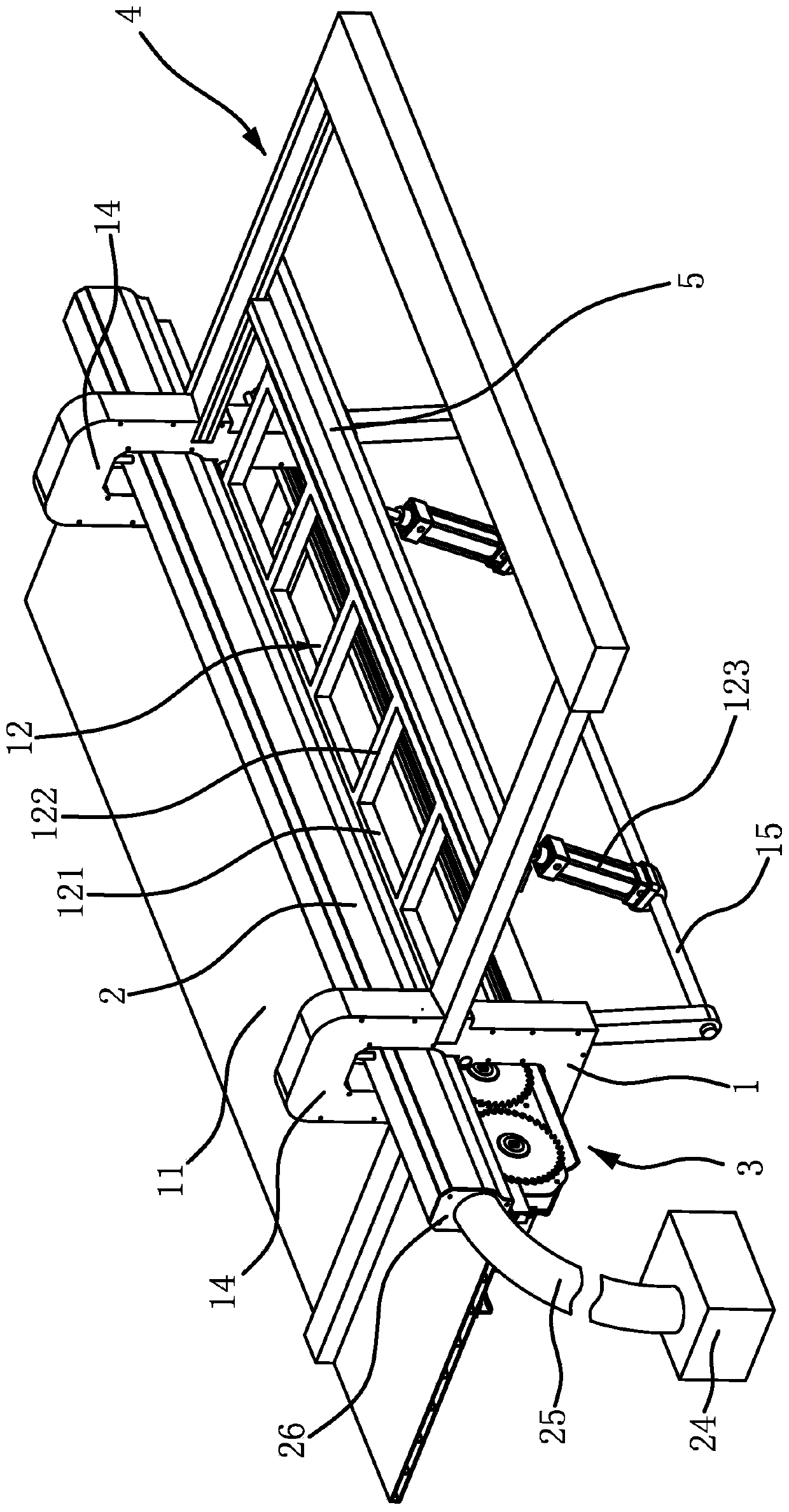
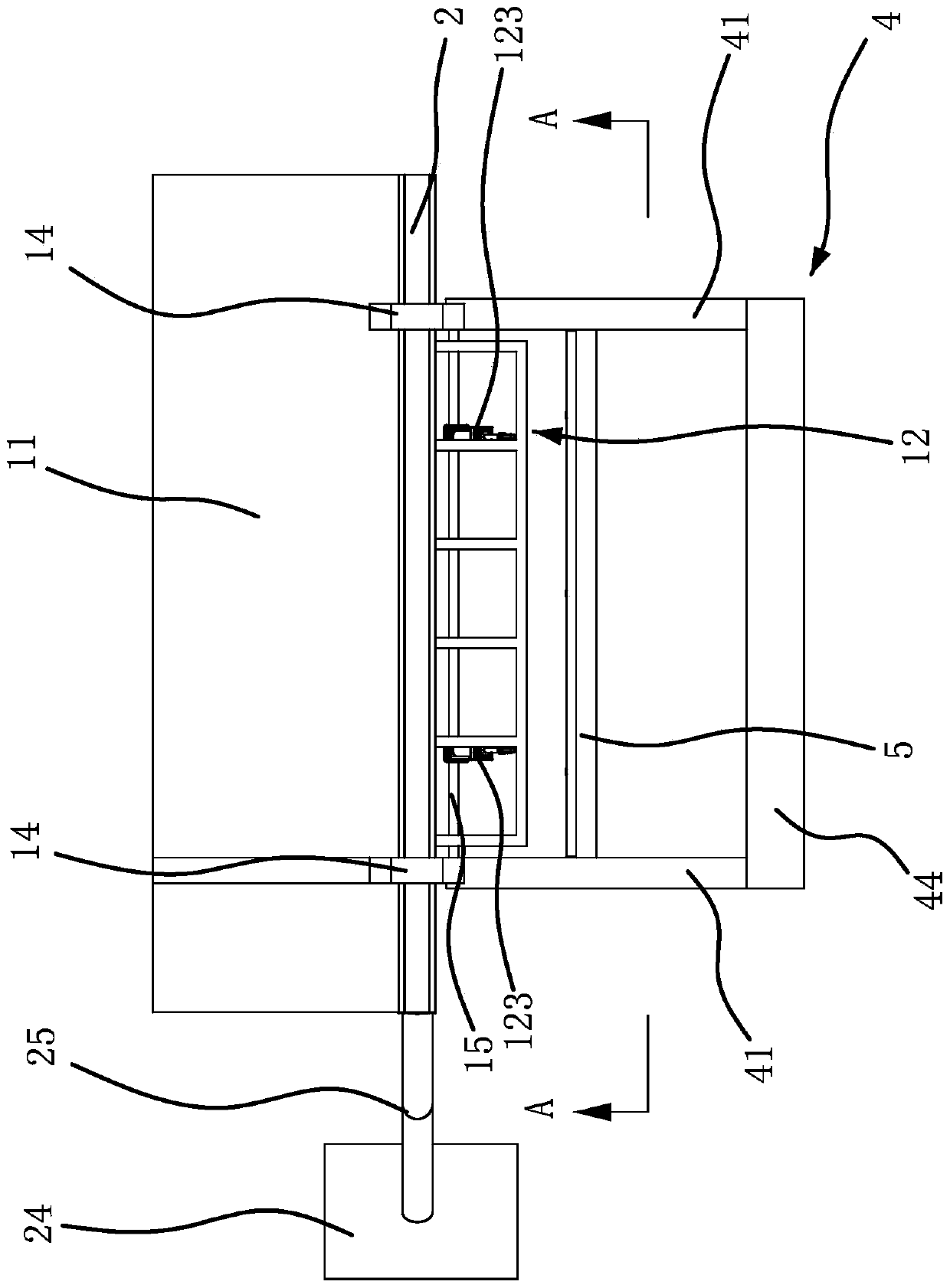
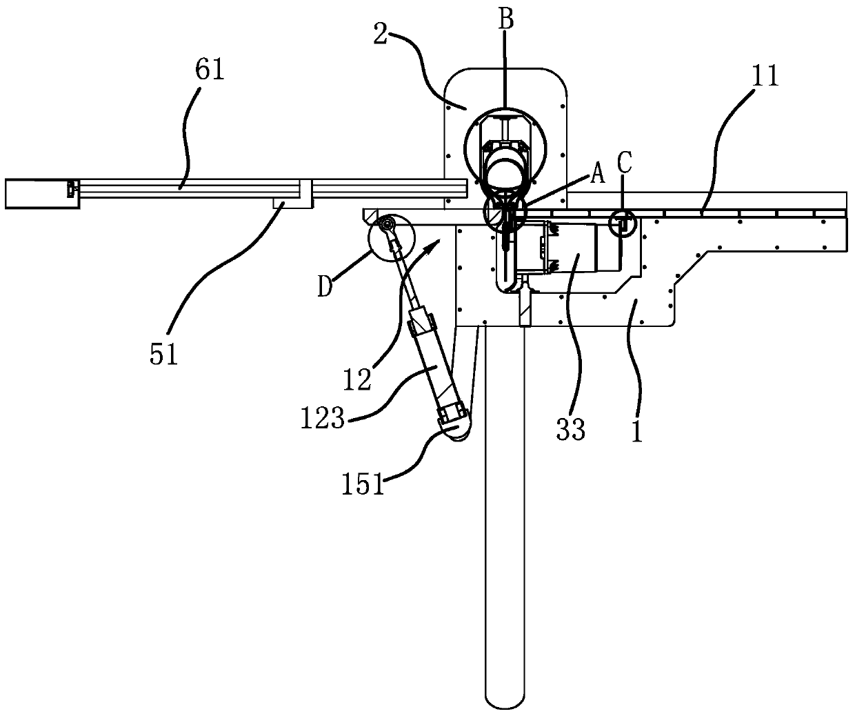
[0044] Such as figure 1 , figure 2 , image 3 and Figure 12 As shown, the sawing machine includes a frame 1, a worktable 11 and a saw head 3. The worktable 11 is horizontally fixed on the frame 1, and the frame 1 is also oscillatingly connected with a blanking frame 12, and the blanking frame 12 swings upwards. When reaching the maximum angle position, the upper side of the blanking rack 12 is flush with the upper surface of the workbench 11, and the blanking rack 12 and the workbench 11 all have straight edges, and the straight edge of the blanking rack 12 and the edge of the workbench 11 The straight edges face each other and form an avoidance gap 13 . The saw head 3 is arranged on the lower surface of the workbench 11 and the saw head 3 can slide along the length direction of the avoidance gap 13 .

[0045] Such as Figure 4 to Figure 6 As shown, the saw head 3 includes a mounting frame 31 and two saw discs 32 that are positioned on the same plane and have gaps. The m...

Embodiment 2

[0058] The structure and principle of this embodiment are basically the same as that of Embodiment 1. The difference is that the drive structure includes a drive motor and a transmission gearbox fixed on the mounting frame. The motor shaft passes through the transmission gearbox and is connected to one of the saw discs. The transmission teeth are fixed on a section of the motor shaft of the drive motor located in the transmission gearbox. The driven gear is connected to the transmission gearbox through the rotation of the shaft. The driven teeth and The transmission teeth are meshed, and one end of the rotating shaft passes through the transmission gear box and is connected with another saw disc.

Embodiment 3

[0060] The structure and principle of this embodiment are basically the same as that of Embodiment 1. The difference lies in that the plate feeding stroke control device includes a stroke control cylinder, the cylinder body of the stroke control cylinder is fixed on the bracket, and the piston rod end of the stroke control cylinder is connected to the The bar is fixed. The position of the stop rod relative to the worktable is controlled by controlling the stretching amount of the piston rod of the stroke control cylinder.


PUM


Abstract

The invention provides a sawing machine and belongs to the field of woodworking machinery. The technical problems that an existing sawing machine is low in cutting efficiency and the like are solved. The sawing machine comprises a rack, a workbench plate and a saw head. The workbench plate is horizontally and fixedly connected to the rack. The rack is further in swinging connection with a blanking frame. The blanking frame and the workbench plate are each provided with a straight-sided edge. The straight-sided edge of the blanking frame and the straight-sided edge of the workbench plate are opposite and form a receding clearance. The saw head is arranged on the lower plate surface of the workbench plate, can slide in the length direction of the receding clearance and comprises two saw plates located on the same plane. The upper edges of the two saw plates penetrate through the receding clearance and are located above the workbench plate. A material-pressing base which can move in the vertical direction is further arranged in the position, located over the receding clearance, of the rack. When the material-pressing base moves downwards and abuts against a workpiece, the upper edges of the saw plates stretch into the material-pressing base. The sawing machine has the advantage of being high in cutting efficiency.

Description

technical field [0001] The invention belongs to the field of woodworking machinery and relates to a sawing machine. Background technique [0002] Woodworking sawing machine is a small sawing machine. At present, the common sawing machine is that the sawing disc is fixed at a certain position on the sawing machine, and then the cutting is realized by pushing the wooden board to move to the sawing disc. Since the position shifts when the wooden board is pushed to move, this kind of sawing machine Cutting accuracy is not high. [0003] In order to improve the cutting accuracy, people have designed a sawing machine with a movable saw head, such as a kind of woodworking sawing machine [publication number CN103358360A] disclosed in Chinese patent literature, by placing the wood to be sawed on the workbench, and then moving the saw head to achieve Cutting, since the movement displacement of the saw head is fixed, it can cut wood precisely. Although the patent uses a movable saw h...

Claims


Application Information

Patent Timeline
Patent Type & Authority Patents(China)
IPC IPC(8): B27B5/065B27B5/18B27B5/29B27B27/02B27B31/08B27G3/00
CPCB27B5/065B27B5/182B27B5/29B27B27/02B27B31/08B27G3/00
Inventor 颜跃
Owner 浙江杭博电动工具有限公司
Why Eureka
Try Eureka