
Height-adjustable corner transport rack

An adjustable and corner-adjustable technology, applied in the direction of transportation and packaging, conveyor objects, etc., can solve the problems of large occupied space, resources, capital consumption, and long conveyor belt length, so as to save space, expand the application area, and set up simply. Effect

Active Publication Date: 2016-06-15
HENAN LONFON IND
View PDF10 Cites 9 Cited by
  • Summary
  • Abstract
  • Description
  • Claims
  • Application Information

AI Technical Summary

Problems solved by technology

Enterprises generally use linear conveyor belts, so the conveyor belt with a certain inclination angle needs to be connected vertically with the high-altitude track when transporting materials, so as to ensure that the materials can be transported to the high-altitude track stably. The general length of the conveyor belt with a certain inclination angle Larger, so this transport method has the problem of occupying too much space
In the prior art, there are also enterprises that use conveyor belts with a certain angle of rotation, so that the inclined straight line of the conveyor belt is parallel to the upper track and the materials are transferred to the upper track, thereby achieving a certain space saving effect, but in the prior art, the The corner part and the straight part are an integral structure, and they are both highly rigid structures. Therefore, a transport device of this type can only be applied to a specific site. After leaving the special site, it is basically a scrap product. Enterprises need to make it according to different needs. Production of conveyor belts with corners of different specifications, resulting in a large amount of resources and capital consumption

Method used


Image

  • Height-adjustable corner transport rack
  • Height-adjustable corner transport rack
  • Height-adjustable corner transport rack

Examples


Embodiment 1

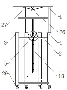
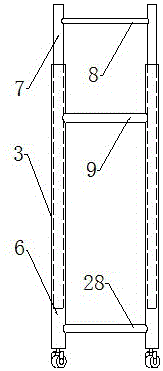
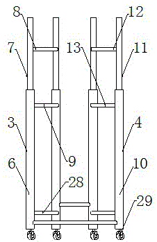
[0027] Such as figure 1 As shown in -7, a height-adjustable corner transfer frame includes a corner transfer mechanism 1 and a lifting mechanism 2, and the corner transfer mechanism 1 is arranged on the top of the lifting mechanism 2, and the lifting mechanism 2 is composed of The lifting frame A3, the lifting frame B4 and the adjustment mechanism 5 arranged between the lifting frame A3 and the lifting frame B4 are composed of two sleeves A6 arranged on the left and right sides and two sleeves arranged on the two sleeves. A6 consists of two elevating rods A7, an auxiliary support rod A8 is horizontally arranged on the upper part between the two elevating rods A7, and a bearing is arranged horizontally on the upper part of the two sleeves A6. Rod A9; the lifting frame B4 is composed of two sleeves B10 arranged on the left and right sides and two lifting rods B11 arranged in the two sleeves B10, and the two lifting rods B11 are separated by their An auxiliary support rod B12 is...


PUM

PropertyMeasurementUnit
Radianaaaaaaaaaa

Abstract

The invention discloses a height-adjustable corner transport rack comprises a corner transport mechanism and a lifting mechanism; the corner transport mechanism is arranged at the top part of the lifting mechanism; the lifting mechanism consists of a lifting scaffold A and a lifting scaffold B; the lifting scaffold A and the lifting scaffold B are structural bodies absolutely identical in structure; a regulating mechanism is arranged between the lifting scaffold A and the lifting scaffold B through a connecting rod and a bearing table; the regulating mechanism consists of a screw, a power output shaft and a drive bearing, wherein the screw is perpendicular to ground, and the power output shaft and the drive bearing are arranged on the bearing table; the corner transport mechanism consists of a fan-shaped frame and drive rollers arranged in the fan-shaped frame; the drive rollers are all conical rollers, and are connected by a drive chain. The height-adjustable corner transport rack disclosed by the invention has the advantages of being adjustable in height, convenient to adjust and move and broad in application range.

Description

technical field [0001] The invention relates to a height-adjustable corner transport frame, which is used for high-altitude cargo transport and cargo transport direction change. Background technique [0002] In the existing technology, enterprises often use high-altitude transportation for material transmission, which can save production space. Therefore, many enterprises need to use conveyor belts with inclination angles to transport materials to high-altitude tracks. Enterprises generally use linear conveyor belts, so the conveyor belt with a certain inclination angle needs to be connected vertically with the high-altitude track when transporting materials, so as to ensure that the materials can be transported to the high-altitude track stably. The general length of the conveyor belt with a certain inclination angle Larger, so this transport method has the problem of occupying too much space. In the prior art, there are also enterprises that use conveyor belts with a cert...

Claims


Application Information

Patent Timeline
IPC IPC(8): B65G47/64
CPCB65G47/641
Inventor 姬利强曹崇敏李常飞
Owner HENAN LONFON IND
Learn More