Converter dust remover adjustment method and control system

A dust removal device and converter dust removal technology, applied in the field of converter dust removal, can solve the problems of inability to dynamically adjust the dust removal effect of the dust removal device, low adjustment accuracy, poor timeliness, etc., and achieve the effect of convenient later query, wide application range, and small changes.

Inactive Publication Date: 2016-06-15
NANJING HENGRUI ENVIRONMENTAL PROTECTION TECH CO LTD
View PDF4 Cites 3 Cited by
  • Summary
  • Abstract
  • Description
  • Claims
  • Application Information

AI Technical Summary

Problems solved by technology

[0005] The technical problem to be solved by the present invention is that the converter dedusting device in the prior art can only manually adjust the dedusting effect, the adjustment accuracy is low, and the timeliness is poor; moreover, the adjustment of the dedusting effect can only meet the national flue gas emission standard as the goal, and cannot dynamically adjust the dedusting Effect to maximize the comprehensive benefits of the dust removal device

Method used


Image

  • Converter dust remover adjustment method and control system
  • Converter dust remover adjustment method and control system
  • Converter dust remover adjustment method and control system

Examples


Embodiment 1

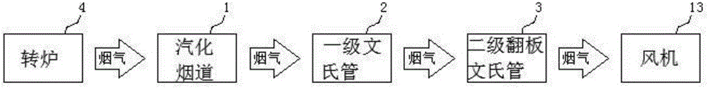
[0059] Such as Figure 10 As shown, this embodiment is an old OG dust removal device that can be automatically adjusted, including a vaporization flue 1, a first-stage venturi tube 2, a second-stage flap venturi tube 3, an online monitoring device 10, a control unit 11, and a human-computer interaction The equipment 12 and fan 13 , the flue gas discharged from the converter 4 passes through the vaporization flue 1 , the first-stage venturi tube 2 , the second-stage flap venturi tube 3 and the fan 13 in sequence.

[0060] A water supply device is designed inside the first-stage venturi tube 2 and the second-stage flap venturi tube 3, and a valve is arranged in the water supply device to control the water supply volume. The furnace mouth of the converter 4 is provided with a pressure sensor for measuring the micro pressure difference at the furnace mouth, and the fan adjusts the speed according to the micro pressure difference measured by the pressure sensor to change the flue g...

Embodiment 2

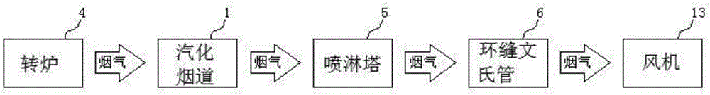
[0065] Such as Figure 11 As shown, this embodiment is a new OG dust removal device that can be automatically adjusted, including a vaporization flue 1, a spray tower 5, an annular venturi tube 6, an online monitoring device 10, a control unit 11, a human-computer interaction device 12 and a fan 13. The flue gas discharged from the converter 4 passes through the vaporization flue 1, the spray tower 5, the annular venturi tube 6 and the fan 13 in sequence.

[0066] A water supply device is designed in the spray tower 5 and the annular venturi tube 6, and a valve is arranged in the water supply device to control the water supply volume. The furnace mouth of the converter 4 is provided with a pressure sensor for measuring the micro pressure difference at the furnace mouth, and the fan adjusts the speed according to the micro pressure difference measured by the pressure sensor to change the flue gas flow velocity in the dust removal device. The opening degree of the annular seam ...

Embodiment 3

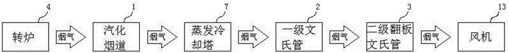
[0071] Such as Figure 12As shown, this embodiment is an old OG semi-dry dust removal device that can be automatically adjusted. The dust removal device of this embodiment is basically the same as that of Embodiment 1, except that an evaporative cooling tower 7 is added between the vaporization flue 1 and the primary venturi tube 2 . The adjustment method and control system of the dust removal device in this embodiment are consistent with those in Embodiment 1.


PUM


Abstract

The invention discloses a converter dust remover adjustment method and control system. By using the adjustment method and control system, the dust content of flue gas treated by the dust remover can be monitored in real time, and the dust removal parameters of the dust remover can be dynamically adjusted, thereby keeping the dust removal effect to be consistent with the preset dust removal effect, and implementing favorable adjustment timeliness and high precision. By using the method and system, the flue gas treated by the converter dust remover can satisfy the environmental protection requirements and compromise the water-saving and power-saving factors of the dust remover, thereby enhancing the comprehensive benefits. Besides, the method and system disclosed by the invention are suitable for various dust removers in the prior art, and thus, have wide applicability; and the method and system only requires small modification on the existing dust remover, and thus, are low in cost.

Description

technical field [0001] The invention relates to the technical field of converter dedusting, in particular to an adjustment method and a control system for a converter dedusting device. Background technique [0002] The flue gas produced by converter steelmaking contains a large amount of dust, which needs to be dedusted, and can only be discharged into the surrounding environment after meeting the national emission requirements. Figure 1 to Figure 9 It is a structural block diagram of different types of dust removal devices in the prior art, which are: old OG dust removal device, new OG dust removal device, old OG semi-dry dust removal device, new OG semi-dry dust removal device, dry electric dust removal device, old OG Wet electrostatic precipitator, new OG wet electrostatic precipitator, old OG semi-dry wet electrostatic precipitator and new OG semi-dry wet electrostatic precipitator. [0003] The dust removal effect of various dust removal devices in the prior art is adj...

Claims


Application Information

Patent Timeline
Patent Type & Authority Applications(China)
IPC IPC(8): C21C5/38C21C5/40
CPCC21C5/38C21C5/40Y02P10/25
Inventor 宫毅
Owner NANJING HENGRUI ENVIRONMENTAL PROTECTION TECH CO LTD
Why Eureka
Try Eureka