Clothes treating apparatus with a heat pump cycle

A clothing treatment device, heat pump cycle technology, applied in washing devices, washing machines with containers, household appliances, etc.

Active Publication Date: 2016-06-15
LG ELECTRONICS INC
View PDF5 Cites 13 Cited by
  • Summary
  • Abstract
  • Description
  • Claims
  • Application Information

AI Technical Summary

Problems solved by technology

[0012] However, the heat pump cycle 4 used in the clothes processing device of the prior art has not played any role for a long time in the washing, rinsing and dehydration processes before the drying process. Therefore, it is urgent to develop a The technical scheme of the heat pump cycle 4

Method used


Image

  • Clothes treating apparatus with a heat pump cycle
  • Clothes treating apparatus with a heat pump cycle
  • Clothes treating apparatus with a heat pump cycle

Examples


no. 1 example

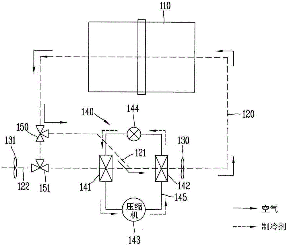
[0069] figure 2 is a schematic diagram of a laundry treatment device with a heat pump cycle 140 according to the first embodiment of the present invention.

[0070] The clothes processing device of the present invention includes: a housing, a drum 110, a circulating air duct 120, a circulating fan 130, a heat pump cycle 140 and a control unit 170 (refer to Figure 5 ).

[0071] The casing constitutes the appearance of the laundry processing device, and the upper end of the casing is provided with a user input unit, a display unit, etc. During laundry, the user can select a variety of functional modes through the user input unit, and can notify the user of the current status through the display unit .

[0072] Drum 110 accommodates laundry and dried laundry. The drum 110 may have a cylindrical shape with a receiving space for receiving objects. The drum 110 is rotatably disposed inside the casing. The front portion of the drum 110 is open, and the front portion of the hou...

no. 2 example

[0127] Figure 7 is a schematic diagram of a laundry treatment apparatus with a heat pump cycle 240 according to a second embodiment of the present invention.

[0128] Figure 7 The illustrated heat pump cycle 240 also includes a second evaporator 249 , a first three-way valve 246 and a second three-way valve 248 connected in parallel. In this embodiment, the control device of the laundry treatment device includes a control unit capable of communicating with various structures of the laundry treatment device. The control unit controls the action of each structural component by sending a control signal to each structural component of the laundry processing device. omit pairing and figure 2 Descriptions of structural components are repeated for illustrative purposes.

[0129] The first evaporator 241 is disposed inside the circulating air duct 220 , and the air flowing out from the drum 210 can pass through the first evaporator 241 .

[0130] In the figure, the second evap...

no. 3 example

[0138] Figure 8 is a schematic diagram of a laundry treatment apparatus with a heat pump cycle 340 according to a third embodiment of the present invention.

[0139] Figure 8 The illustrated heat pump cycle 340 also includes a second evaporator 349, a first three-way valve 346, a second three-way valve 348, and a second expansion valve 344b connected in series. In this embodiment, the control device of the laundry treatment device includes a control unit capable of communicating with various structures of the laundry treatment device. The control unit controls the action of each structural component by sending a control signal to each structural component of the laundry processing device. Omit here and figure 2 Descriptions of structural elements that are repeated for illustrative purposes.

[0140] The first evaporator 341 is disposed inside the circulating air duct 320 , and the air flowing out from the drum 310 can pass through the first evaporator 341 .

[0141] Th...


PUM


Abstract

A clothes treating apparatus having a heat pump cycle for performing a washing cycle and a drying cycle is provided. The clothes treating apparatus may include a drum configured to accommodate a item to be treated; a heat pump cycle having a first evaporator, a compressor, a condenser, and an expansion valve to heat air introduced into the drum; a circulation duct configured to form a circulation passage of air that has passed through the drum; a circulation fan configured to circulate the air; and a controller configured to drive the heat pump cycle and the circulation fan during the washing cycle to preheat at least one of the drum or the circulation duct.

Description

technical field [0001] The present invention relates to a laundry treatment device having a heat pump cycle capable of shortening drying time by preheating before starting a drying course. Background technique [0002] Generally, a clothes processing device with a drying function such as a washing machine or a dryer puts the laundry in the state where the washing and dehydration process is completed into the drum, and supplies hot air to the inside of the drum to evaporate the moisture of the laundry to dry the laundry. object device. [0003] Clothes dryers can be classified into exhaust-type clothes dryers and condensation-type clothes dryers according to how humid air passing through a drum is treated after drying laundry. [0004] The exhaust type clothes dryer discharges the humid air that comes out of the drum to the outside of the dryer, and the condensation type clothes dryer does not discharge the humid air that comes out of the drum to the outside of the dryer, bu...

Claims


Application Information

Patent Timeline
Patent Type & Authority Applications(China)
IPC IPC(8): D06F25/00D06F58/20
CPCD06F25/00D06F39/088D06F58/20D06F58/206D06F58/30D06F2103/36D06F2103/50D06F2105/24D06F2105/26
Inventor 柳秉助朴大润李勇柱
Owner LG ELECTRONICS INC
Why Eureka
Try Eureka