Full-automatic roof leakage finding and repairing robot and leakage finding and repairing method
A fully automatic, robotic technology that can be used in areas such as detection of fluid occurrence at leak points, building maintenance, and liquid/vacuum tightness measurement. It can solve the problems of manual operation, high cost, and achieve low overall cost and Simple principle, significant effect
- Summary
- Abstract
- Description
- Claims
- Application Information
AI Technical Summary
Problems solved by technology
Method used
Image
Examples
Embodiment 1
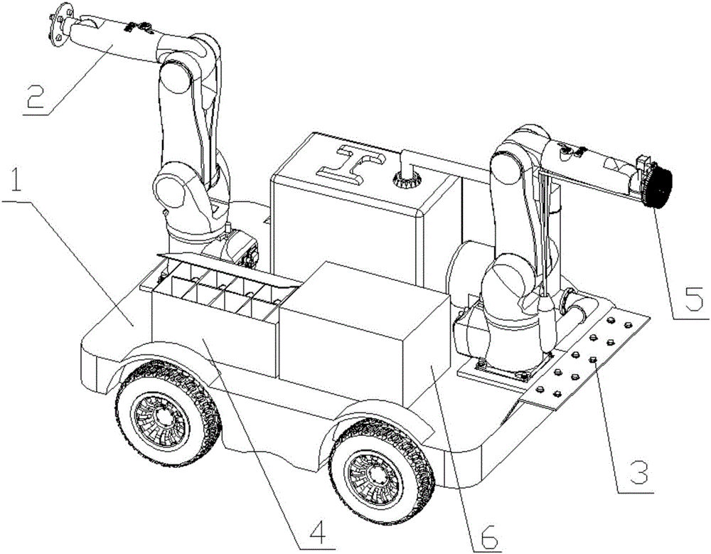
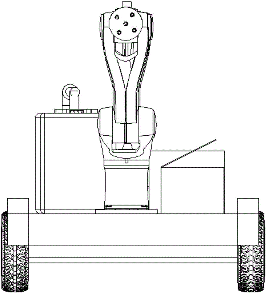
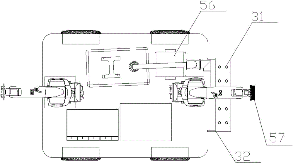
[0034] A fully automatic robot for checking and repairing leaks on the roof, comprising: a chassis drive platform 1, a microwave directional emission module 2, an infrared temperature directional detection mechanism 3, a control and electric drive mechanism 4, a leak repairing mechanism 5 and a power lithium battery pack 6.
Embodiment 2
[0036] The microwave directional launch module 2 includes: a microwave directional launcher 21 , a microwave directional launch turntable 22 , a microwave directional launch mechanical arm 23 , a microwave directional launch base 24 , and a microwave directional launch servo motor 25 . There are five microwave directional transmitters 21 in total, arranged in a matrix and evenly distributed on the microwave directional transmitter turntable 22 . The movement of the microwave directional transmitter turntable 22 can drive the movement of the microwave directional transmitter 21 . At the same time, the microwave directional launch turntable 22 is connected to the top of the microwave directional launch manipulator 23, and the end of the microwave directional launch manipulator 23 is connected to the microwave directional transmitter base 24, and the microwave directional transmitter base 24 is installed and fixed on the chassis drive platform through a bolt and nut structure. 1 o...
Embodiment 3
[0038] The infrared temperature orientation detection mechanism 3 includes: an infrared temperature sensing matrix 31 and a bracket 32 . The infrared temperature sensing matrix 31 is installed and fixed on the bracket 32 , and the bracket 32 is fixedly installed on the rear end of the chassis driving platform 1 . Wherein, the direction of the probe of the infrared temperature sensing matrix 31 is downward, that is, the direction is toward the ground. The infrared temperature orientation detection mechanism 3 is connected with the CPU controller 41 .
PUM
 Abstract
Description
Claims
Application Information
 - R&D
- Intellectual Property
- Life Sciences
- Materials
- Tech Scout
- Unparalleled Data Quality
- Higher Quality Content
- 60% Fewer Hallucinations
Browse by: Latest US Patents, China's latest patents, Technical Efficacy Thesaurus, Application Domain, Technology Topic, Popular Technical Reports.
© 2025 PatSnap. All rights reserved.Legal|Privacy policy|Modern Slavery Act Transparency Statement|Sitemap|About US| Contact US: help@patsnap.com


