
A mining-filling combined with continuous mining mining method in stage mines

A mining method and stage technology, applied in surface mining, mining equipment, underground mining, etc., can solve the problems of safety production threat, low production capacity, high labor intensity, reduce loss and dilution rate, improve production capacity, and achieve continuous sexual effect

Inactive Publication Date: 2018-08-21
WUHAN UNIV OF SCI & TECH
View PDF7 Cites 0 Cited by
  • Summary
  • Abstract
  • Description
  • Claims
  • Application Information

AI Technical Summary

Problems solved by technology

Although the stage mining method has the advantages of large production capacity, high mining efficiency, and simple mining process structure, but with the continuous advancement of mining work, the goaf formed in the stope will become larger and larger, which will affect the ground. The management and control of pressure may cause different degrees of surface subsidence and subsidence. Subsidence will bring serious threats to the environment of the mining area and the safety of industrial and agricultural production in the mining area. The dilution rate increases, and the ventilation environment of the stope becomes poor
[0003] As the country pays more and more attention to the environment and safety of mining areas, it is a new development trend of mining to combine the stage mine mining method and filling mining method to realize continuous mining of mines. There is still a production capacity in mining by simply using the filling mining method Small size, low recovery rate, complex recovery process structure, high labor intensity and other defect technologies are not suitable for the mining of thick and large ore bodies. Only the characteristics of stage mine mining method and filling mining method can be fully combined according to the actual conditions of the mine. Only in this way can the continuous mining of mines be realized, the capacity of mine production can be improved, and the safety of mine production can be guaranteed.

Method used


Image

  • A mining-filling combined with continuous mining mining method in stage mines
  • A mining-filling combined with continuous mining mining method in stage mines
  • A mining-filling combined with continuous mining mining method in stage mines

Examples


Embodiment Construction

[0016] The present invention will be further described below in conjunction with the accompanying drawings and specific embodiments, and the embodiments in the embodiments will be described by taking mining in a mining area divided into three mining stages as an example.

[0017] A stage mine mining method combining mining and filling with continuous mining, the steps are as follows:

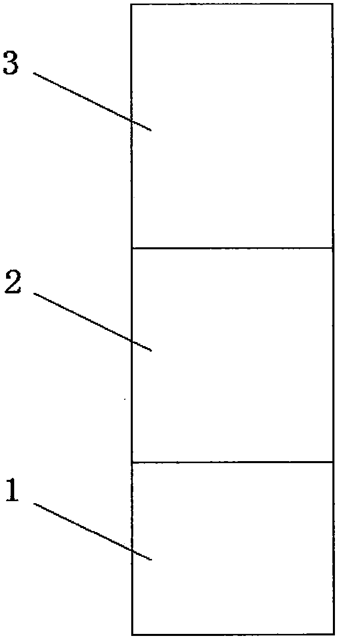
[0018] (I) if figure 1 As shown, according to the actual situation of the area to be mined, the area to be mined is divided into several mining stages from bottom to top;

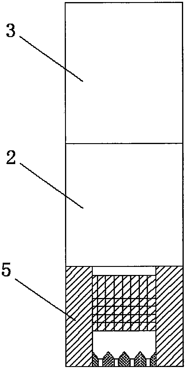
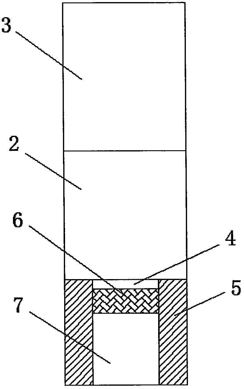
[0019] (II) adopting stage mining method to carry out rock drilling and blasting to the first mining stage to get out of mine (see figure 2 ), and finally in the first mining stage, rock drilling chambers, gobs, ore pillars and top layers are formed (see image 3 );

[0020] (III) If Figure 4 As shown in Fig. 1, rock drilling and blasting is adopted for mining in the second mining stage, and an isolation zone is reserve...


PUM


Abstract

The invention relates to a mining-filling combined continuous mining sublevel room mining method. The method comprises dividing a mining zone to be mined into multiple mining sections, orderly carrying out stoping on the mining sections from bottom to top through a sublevel room mining method, and in stoping, simultaneously, filling goafs with a mixed filling material of waste surrounding rock produced through drilling and blasting in the previous mining stage and mortar until mining and filling processes are finished in the whole mining zone to be mined. In mining through the sublevel room mining method, stoping and filling are combined and are carried out simultaneously so that mining continuity is realized, a mining production capacity is improved, mining safety is guaranteed, waste stones produced through mining are fully used and an ore loss and dilution rate is reduced.

Description

【Technical field】 [0001] The invention relates to the technical field of mining, in particular to a stage mining method in which mining and charging are combined with continuous mining. 【Background technique】 [0002] Since the 1980s, more than 55% of large and medium-sized mines in my country have been mined using the stage mining method. The first step is to return to the mining room, and the second step is to return to the mining pillar. When returning to mining, the stope exists in the form of a goaf, and the stope only relies on the strength of the ore pillar and surrounding rock itself for support and maintenance. Although the stage mining method has the advantages of large production capacity, high mining efficiency, and simple mining process structure, but with the continuous advancement of mining work, the goaf formed in the stope will become larger and larger, which will affect the ground. The management and control of pressure may cause different degrees of surfac...

Claims


Application Information

Patent Timeline
Patent Type & Authority Patents(China)
IPC IPC(8): E21C41/16E21F15/00F42D3/04
CPCE21C41/16E21F15/005F42D3/04
Inventor 杨明财盛建龙李丹天翟明洋董舒吴恩桥
Owner WUHAN UNIV OF SCI & TECH
Learn More