Wind and water generator

A generator and feng shui technology, applied in hydroelectric power generation, engine components, impact engines, etc., can solve problems such as manufacturing difficulties, complex structures, and increased power generation costs, and achieve easy start-up, large moment of inertia, water saving and high-pressure gas Effect

Inactive Publication Date: 2016-06-15
柳海源
View PDF7 Cites 0 Cited by
  • Summary
  • Abstract
  • Description
  • Claims
  • Application Information

AI Technical Summary

Problems solved by technology

[0004] (1) The speed change of the speed change device must be adjusted with the change of wind force. If there is a time difference in the speed regulation after the wind changes, the speed may be too high in an instant, and the voltage may increase sharply and damage the power transmission circuit.
[0005] (2) The speed change device requires high precision, fast and stable speed change, complex structure, complicated speed change, and several kinds of speed change and voltage change at the same time, so the manufacturing cost is high, and the fault is easy to be damaged.
[0006] (3) All the weight is concentrated at high altitude, which makes it difficult to erect and maintain, which increases the cost of power generation
[0008] (1) Using high-pressure air to impel the turbine requires a large amount of high-pressure airflow. Generally, after storage and storage, the support time is relatively short
[0009] (2) If a large-volume high-pressure storage tank is built, the high-pressure sealing requirements are safe and reliable, and its material, thickness, and structure requirements are relatively high, it is difficult to form, difficult to manufacture, high cost ratio, and poor economic applicability

Method used


Image

  • Wind and water generator
  • Wind and water generator

Examples


Embodiment Construction

[0023] In order to make the object, technical solution and advantages of the present invention more clear, the present invention will be further described in detail below in conjunction with the accompanying drawings and embodiments. It should be understood that the specific embodiments described here are only used to explain the present invention, not to limit the present invention.

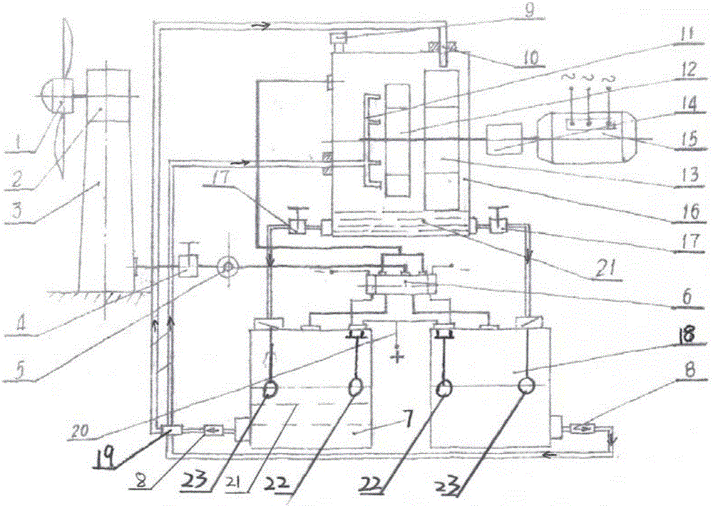
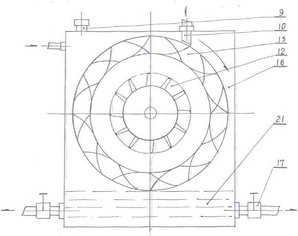
[0024] An embodiment of the present invention provides a wind water generator, such as figure 1 , 2 As shown, the wind water generator includes a wind wheel 1, an air compressor 2, a pressure storage column 3, an electromagnetic distributor 6, a high-pressure turbine nozzle 11, a hydraulic turbine 12, a water wheel 13, a transmission 14, a generator 15, and a water tank 16 , the wind wheel 1 is connected to the air compressor 2 arranged in the pressure storage column 3, the pressure storage column 3 communicates with the electromagnetic distributor 6 through the gas pipeline, and the electromag...


PUM


Abstract

The invention discloses a wind and water generator. A wind wheel is connected with an air compressor arranged in a pressure storage stand column. The pressure storage stand column communicates with an electromagnetic distributor through a gas pipeline. The electromagnetic distributor communicates with a first container and a second container through two gas pipelines and communicates with a water tank through one gas pipeline, wherein the first container and the second container are arranged below the electromagnetic distributor, and the water tank is arranged above the electromagnetic distributor. The side face of the first container and the side face of the second container communicate with the water tank through high-pressure water pipes and a cross-shaped four-way joint. the ail end of one path of the cross-shaped four-way joint is connected with a high-pressure turbine nozzle arranged in the water tank and located on one side of a water pressure turbine, and the tail end of the other path of the cross-shaped four-way joint is connected with a water cart nozzle arranged in the water tank and located above a water cart. The water pressure turbine and the water cart are connected through the same rotating shaft, and the rotating shaft is further provided with a speed changer and a generator body which are located outside the water tank. According to the wind and water generator, the high-pressure air flow is converted into the high-pressure water flow, an ideal power source is obtained, fluid water can be repeatedly and circularly used, and water and high-pressure gas are saved.

Description

technical field [0001] The invention belongs to the technical field of green renewable energy power generation, and in particular relates to a wind water generator. Background technique [0002] The current wind power generation device directly drives the generator to generate electricity after the wind wheel rotates through variable speed and speed regulation, or the wind wheel drives the press to compress the air and store the pressure, then impels the turbine to drive the generator to generate electricity after the speed is changed. Fengshui energy conversion power generation related technologies appeared. [0003] The rotation of the wind wheel directly drives the generator to generate electricity after the speed is adjusted. Since the wind is an irregular and variable air flow, the transmission must change the speed according to the dynamic and complicated strains to achieve the rated speed required by the generator and stabilize the voltage. It has the following techn...

Claims


Application Information

Patent Timeline
Patent Type & Authority Applications(China)
IPC IPC(8): F03B1/00F03B15/20F03D9/17
CPCF03B1/00F03B15/20F05B2220/706Y02E10/20Y02E70/30
Inventor 柳海源
Owner 柳海源
Why Eureka
Try Eureka