
A double-acting multi-stage anti-rotation hydraulic cylinder

A double-acting, hydraulic cylinder technology, applied in the field of hydraulic cylinders, can solve the problems of high production cost, large processing difficulty, large space occupation, etc., and achieves the effects of easy processing, low cost, and satisfying use requirements.

Active Publication Date: 2017-09-12
BEIJING INST OF SPACE LAUNCH TECH +1
View PDF7 Cites 0 Cited by
  • Summary
  • Abstract
  • Description
  • Claims
  • Application Information

AI Technical Summary

Problems solved by technology

[0004] In order to solve the problems of difficult processing, high production cost, poor versatility and large space occupied by the hydraulic cylinder anti-rotation technology in the prior art, the invention provides a double-acting multi-stage anti-rotation hydraulic cylinder, which includes a shell, The rear end cover and the piston rod, wherein the outer circumference of the piston rod is provided with a cylinder, the piston rod and the cylinder are coaxially installed in the inner cavity of the housing, and the rear end cover is fixedly installed on the rear end of the housing. There is a positive cavity oil port on the end cover, which connects the positive cavity oil port with the positive cavity oil chamber of the piston rod and cylinder barrel. The anti-cavity oil chamber is connected, and also includes a piston rod anti-rotation assembly with a telescopic rod structure. The rear end of the component is fixedly connected to the rear end cover

Method used


Image

  • A double-acting multi-stage anti-rotation hydraulic cylinder
  • A double-acting multi-stage anti-rotation hydraulic cylinder
  • A double-acting multi-stage anti-rotation hydraulic cylinder

Examples


Embodiment Construction

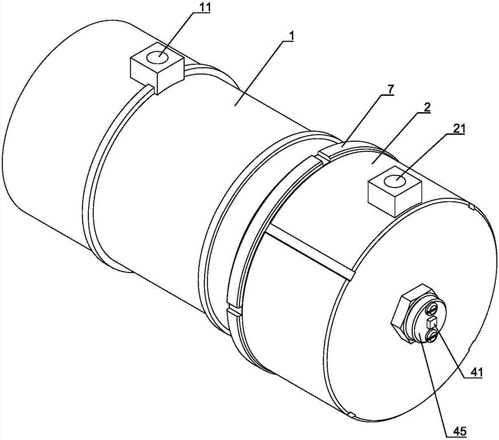
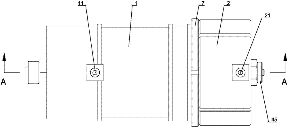
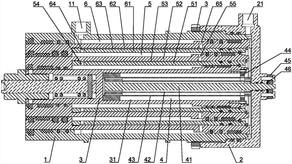
[0065] Such as Figure 1 to Figure 44 Shown is a specific embodiment of a double-acting multi-stage anti-rotation hydraulic cylinder of the present invention, which generally includes a housing 1 , a rear end cover 2 and a piston rod 3 . A cylinder is sheathed on the outer circumference of the piston rod 3, and the piston rod 3 and the cylinder are coaxially installed in the inner cavity of the housing 1, and the rear end cover 2 is fixedly installed on the rear end of the housing 1. The positive cavity oil port 21 is set on the rear end cover 2, and the positive cavity oil port 21 is always connected with the positive cavity oil chamber of the piston rod 3 and the cylinder barrel, and the reverse cavity oil port 11 is set on the shell 1, and the reverse cavity The oil port 11 is always in communication with the anti-cavity oil chamber of the piston rod 3 and the cylinder barrel. At the same time, the piston rod anti-rotation assembly 4 of the telescopic rod structure is set,...


PUM


Abstract

The invention discloses a double-action multistage anti-rotation hydraulic cylinder which comprises a housing, a rear end cover, and a piston rod, and further comprises a piston rod anti-rotation assembly, wherein a cylinder barrel sleeves the piston rod; the piston rod and the cylinder barrel are concentrically mounted in an inner cavity of the housing; the rear end cover is fixedly mounted at the rear end of the housing; a positive cavity oil opening is formed in the rear end cover and can be communicated with the piston rod and a positive cavity oil chamber of the cylinder barrel; a reverse cavity oil opening is formed on the housing and can be communicated with the piston rod and a reverse cavity oil chamber of the cylinder barrel; the piston rod anti-rotation assembly is of a telescopic rod structure; the front end of the piston rod anti-rotation assembly is arranged in a guide groove which is formed in the middle on the rear end surface of the piston rod in the front-and-back direction; the rear end of the piston rod anti-rotation assembly is fixedly connected with the rear end cover. The double-action multistage anti-rotation hydraulic cylinder has the advantages of being simple in structure, easy in process, low in cost and small in size. The hydraulic cylinder disclosed by the invention can fulfill multiple technical aims of double actions, a large stroke and rotation prevention.

Description

technical field [0001] The invention relates to a hydraulic device, in particular to a double-acting hydraulic cylinder capable of preventing rotation. Background technique [0002] Hydraulic cylinders are important actuators in hydraulic systems and are widely used in various fields. In many occasions, due to the limitation of installation space and stroke, it is often necessary to use multi-stage hydraulic cylinders to meet the requirements of small installation space and large stroke; and for some other applications, it is required that the hydraulic cylinder cannot Rotation occurs so that the device it drives maintains its direction. At present, the methods to solve the anti-rotation of hydraulic cylinders in this field mainly use non-circular special-shaped cylinders and piston rod structures and external guiding anti-rotation mechanisms, but these two methods have many problems due to their own structural defects, mainly in the following aspects: The following aspect...

Claims


Application Information

Patent Timeline
Patent Type & Authority Patents(China)
IPC IPC(8): F15B15/16F15B15/20
CPCF15B15/1423F15B15/149F15B15/16F15B15/20
Inventor 陈奇郭小强李玉顺杨运岭刘薇
Owner BEIJING INST OF SPACE LAUNCH TECH
Learn More