Micro-flow labyrinth bypassing pressure adjusting and stabilizing valve

A micro-flow, pressure-stabilizing valve technology, applied in the valve's device for absorbing fluid energy, sliding valve, valve details, etc., can solve the problems of low safety and reliability, large maintenance workload, complex system structure, etc. The effect of technical level, less maintenance workload, scientific and reasonable structure

Inactive Publication Date: 2016-06-15
HUNAN DATANG ENERGY SAVING SCI & TECH CO LTD
View PDF7 Cites 2 Cited by
  • Summary
  • Abstract
  • Description
  • Claims
  • Application Information

AI Technical Summary

Problems solved by technology

The existing known technology and the current situation have many deficiencies, defects and disadvantages such as relatively large system, difficult installation, complex system structure, more control and protection, low safety and reliability, and large maintenance workload.

Method used


Image

  • Micro-flow labyrinth bypassing pressure adjusting and stabilizing valve
  • Micro-flow labyrinth bypassing pressure adjusting and stabilizing valve

Examples


Embodiment Construction

[0024] The present invention will be described in detail below in conjunction with the accompanying drawings. As shown in the accompanying drawings:

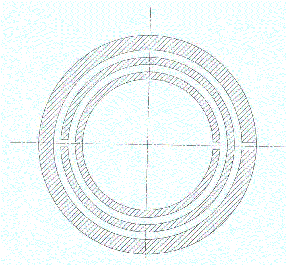
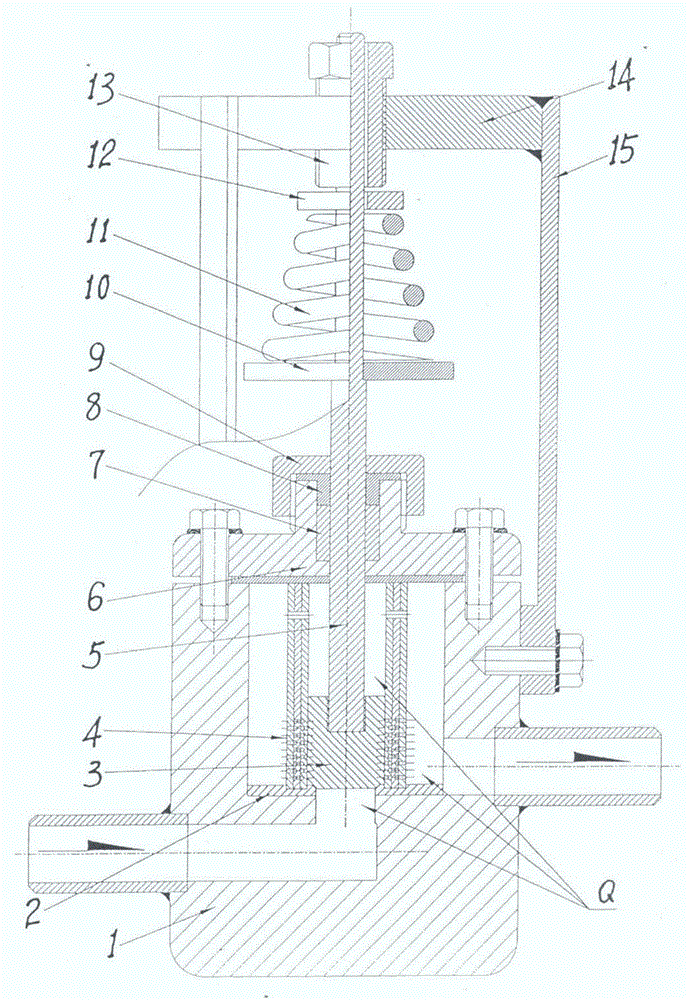
[0025] A micro-flow labyrinth bypass type pressure regulating and stabilizing valve, which consists of a valve body 1, a valve core seat 2, a valve core 3, a bypass labyrinth body 4, a valve stem 5, a valve cover 6, a packing 7, a pressure ring 8, a pressure Cap 9, balance plate 10, spring 11, limit ring 12, trimming knob 13, top plate 14, support 15 constitute;

[0026]The micro-flow labyrinth bypass pressure regulating and stabilizing valve, the bottom end of the chamber of the valve body 1 is inlaid with the valve core seat 2, and the upper end of the valve body 1 is connected to the valve cover 6, the valve core seat 2 and the bypass labyrinth body 4 The bottom ends are all fixedly connected, and the bottom surface of the bonnet 6 is connected with the upper end of the flow-around labyrinth body 4 by pressing against each o...


PUM


Abstract

The invention discloses a micro-flow labyrinth bypassing pressure adjusting and stabilizing valve, and relates to the technical field of valves. A key technology of setting a bypassing labyrinth body is adopted; the bottom end of a cavity of a valve body is inlaid with a valve core base; the upper end of the valve body and a valve cover are fixed, and the valve core base and the bottom end of the bypassing labyrinth body are fixed; the bottom surface of the valve cover is buttedagainst the upper end of the bypassing labyrinth body;the inner wall of the bypassing labyrinth body and a valve element relatively slide; the upper end of the valve element and the bottom end of a valve rod are fixed, and the upper position of the middle section of the valve rod and a balance disc are fixed; a filler and a pressure ring are put in a valve cover trapezoidal hole in the lower position of the middle section of the valve rod; the upper end of the valve cover is fixed toa pressure cap; the valve rod and a limiting ring relatively slide; the lower end of a spring inserted in the valve rod and the balance disc are butted against, and the upper end of the spring and a limiting ring are butted against; the upper end of the valve rod and a fine-adjustment twisting internal threadare in threaded connection, and a fine-adjustment twisting external thread and a top plate are in threaded connection; the top plate is welded with a support; and the support is fixed tothe side surface of the valve body. The valve is used for a boiler less-oil or micro-oil ignition fuel system of a fire coal thermal power plant. The valve is simple and skillful in structure, stable and reliable in effect, easy to produce and low in cost.

Description

technical field [0001] The invention relates to a micro-flow labyrinth bypass type pressure regulating and stabilizing valve, which relates to the technical field of valves; Background technique [0002] At present, in the "low-oil ignition" or "micro-oil ignition" system of coal-fired thermal power plant boilers, in order to save a lot of fuel and at the same time, for high atomization and high combustion rate of fuel, it is necessary to use low-flow high-performance gasification small Oil gun, the small oil gun has a small output, requires low oil pressure (0.6-1MPa) and needs to be stable, but the oil pressure (3.5-2.5MPa) of the power plant boiler fuel system and all pressure regulating valves on the market cannot meet the requirements The need for a small grease gun. In order to meet the needs of small oil guns and realize "low oil ignition" or "small oil ignition" of coal-fired thermal power plant boilers, the current conventional methods are to add "storage oil ignit...

Claims


Application Information

Patent Timeline
Patent Type & Authority Applications(China)
IPC IPC(8): F16K17/30F16K3/24F16K3/314F16K27/04F16K41/02F16K47/08
CPCF16K3/246F16K3/314F16K17/30F16K27/041F16K41/02F16K47/08
Inventor 郭文生邓伟力
Owner HUNAN DATANG ENERGY SAVING SCI & TECH CO LTD
Why Eureka
Try Eureka