
Integrated settlement monitoring apparatus based on optical fiber F-P cavity pressure sensor

A pressure sensor and subsidence monitoring technology, which is applied to measuring devices, pressure difference measurement between multiple valves, and fluid pressure measurement, etc. It can solve complex installation and debugging, cumbersome installation, and limited signal transmission distance of electrical pressure sensors. problem, to achieve the effect of simple structure, convenient transportation and installation

Active Publication Date: 2016-06-15
CHINA GEOKON INSTR
View PDF8 Cites 6 Cited by
  • Summary
  • Abstract
  • Description
  • Claims
  • Application Information

AI Technical Summary

Problems solved by technology

However, the structure of this type of device is very complicated to install and debug due to the large number of pipelines, and the signal transmission distance of the electric pressure sensor is limited, and there are the following disadvantages: 1) Each monitoring point must be equipped with a liquid pipe, a vent pipe, For signal transmission cables, the more monitoring points, the more pipelines are configured, the installation is cumbersome, and the protection is also difficult; 2) The measuring range of the electric pressure sensor is inversely proportional to the measurement resolution, and the application range is limited; 3) Due to the use of electrical signal transmission, Susceptible to lightning strikes or electromagnetic interference; 4) and the transmission distance is limited, usually below a kilometer

Method used


Image

  • Integrated settlement monitoring apparatus based on optical fiber F-P cavity pressure sensor
  • Integrated settlement monitoring apparatus based on optical fiber F-P cavity pressure sensor
  • Integrated settlement monitoring apparatus based on optical fiber F-P cavity pressure sensor

Examples


Embodiment Construction

[0025] The present invention will be described below in conjunction with the drawings.

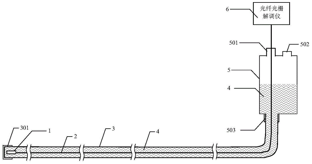
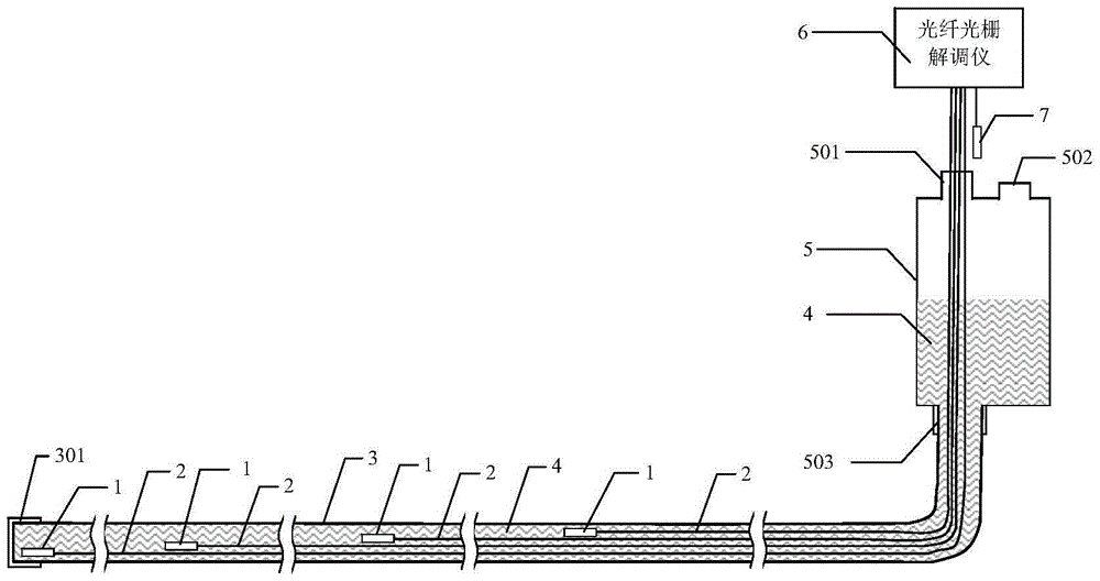
[0026] The invention relates to an integrated settlement monitoring device based on an optical fiber F-P cavity pressure sensor, and its structure is as follows figure 2 As shown, it includes a miniature optical fiber FP cavity pressure sensor 1, an optical fiber 2, a liquid pipe 3, a liquid storage container 5, and a fiber grating demodulator 6. The miniature optical fiber FP cavity pressure sensor 1 is installed in the pipe of the liquid pipe 3, and the storage The bottom end of the liquid container 5 is provided with a liquid pipe interface 503 and communicates with one end of the liquid pipe 3 through the liquid pipe interface 503, the other end of the liquid pipe 3 is sealed, and the liquid storage container 5 is provided with an optical fiber outlet hole 501 and The liquid injection hole 502 can be opened and closed. The micro-fiber FP cavity pressure sensor 1 passes through the optical...


PUM

PropertyMeasurementUnit
Diameteraaaaaaaaaa
The inside diameter ofaaaaaaaaaa

Abstract

The invention provides an integrated settlement monitoring apparatus based on an optical fiber F-P cavity pressure sensor. The apparatus includes a micro optical fiber F-P cavity pressure sensor, an optical fiber, a liquid passing tube, a liquid storage container and a fiber bragg grating demodulation instrument. The micro optical fiber F-P cavity pressure sensor is installed in a pipeline of the liquid passing tube and passes through the liquid storage container from the pipeline of the liquid passing tube through a liquid passing tube port and an optical fiber outlet hole through the optical fiber and is lead out to the fiber bragg grating demodulation instrument. Pressure transmission liquid is arranged in the liquid passing tube and the liquid storage container. The liquid level in the pressure transmission liquid is higher than that in the micro optical fiber F-P cavity pressure sensor. The apparatus is simple in structure, is convenient to install, has long distance of transmission and has high measurement reliability. The apparatus can be used in settlement monitoring on a tailing dam and various rock and soil bodies under harsh environmental conditions.

Description

Technical field [0001] The invention relates to the technical field of geotechnical and engineering structure safety monitoring, in particular to an integrated settlement monitoring device based on an optical fiber FP cavity pressure sensor. The relative settlement monitoring. Background technique [0002] In the field of geotechnical and engineering structural safety monitoring, there are two types of traditional soil or structure settlement monitoring equipment that can be remotely transmitted: hydraulic settlement gauges based on pressure sensors suitable for buried installation and static level gauges suitable for surface installation. However, these devices have large range and low resolution, or high resolution but small range, which greatly limits their application environment. In addition, there are problems such as cumbersome installation or assembly due to more large-sized components. [0003] The structure of the traditional settlement monitoring device using the princi...

Claims


Application Information

Patent Timeline
IPC IPC(8): G01C5/00G01L13/00
CPCG01C5/00G01L13/00
Inventor 谭斌
Owner CHINA GEOKON INSTR
Learn More