Check patentability & draft patents in minutes with Patsnap Eureka AI!

Absolute capacitive rotary encoder

A rotary encoder and absolute capacitance technology, which is applied in the direction of converting sensor output, instruments, and using electric/magnetic devices to transfer sensing components, etc., can solve the problems of not considering error sources and insufficient high-precision requirements

Active Publication Date: 2016-06-15
HEXAGON TECH CENT GMBH
View PDF12 Cites 7 Cited by
  • Summary
  • Abstract
  • Description
  • Claims
  • Application Information

AI Technical Summary

Problems solved by technology

A disadvantage of the rotary encoder according to US6940278B2 is that the compensation of the above-mentioned errors is insufficient for the high precision requirements associated with the determination of the angle
Furthermore, another disadvantage is that additional sources of error (such as electronics or deformation of the rotor disk) which in principle cannot be compensated by differential compensation are not taken into account; in other words, only a small part of the error spectrum is compensated

Method used


Image

  • Absolute capacitive rotary encoder
  • Absolute capacitive rotary encoder
  • Absolute capacitive rotary encoder

Examples


Embodiment Construction

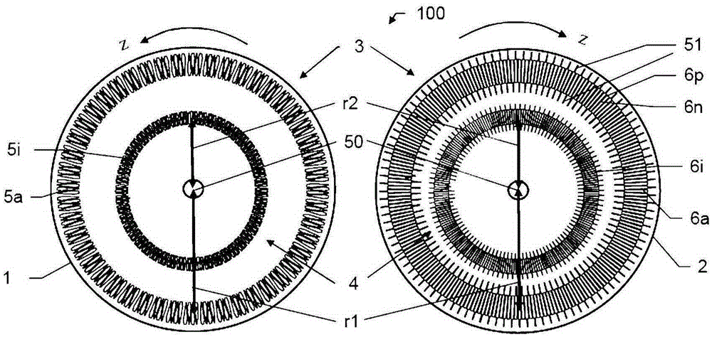
[0054] figure 1 A rotary encoder 100 according to the invention is shown comprising a first disc 1 , denoted below as stator 1 , and a second disc 2 , denoted below as rotor 2 . The stator 1 and the rotor 2 are arranged coaxially and at a distance from each other on a measuring axis 50 , rotatable relative to each other about the measuring axis 50 . However, in accordance with figure 1In the illustration of , for clarity, the rotary encoder is "folded open", i.e. both the stator 1 and the rotor 2 are in the plane of the drawing, and as a result, the facing areas of discs 1 and 2 are visible. The rotary encoder 100 has a first sensor ring 3 with: a plurality of first coupling electrodes 5a, which in this example are realized as transmitting electrodes and are arranged in a ring-shaped manner on the stator 1; Two coupling electrodes 6 a are realized in this example as receiving electrodes and are arranged in a ring-shaped manner on the rotor 2 . In addition, the rotary encode...


PUM


Abstract

The invention provides an absolute capacitive rotary encoder(100) comprising a first disk(1), which is rotatable relative a second disk(2), and a first sensor ring(3) and a second sensor ring(4). The first(3) and the second sensor ring(4) each have a multiplicity of first coupling electrodes (5a, 5i, 5R-5U)and second coupling electrodes(6a, 6i, 6p,6n) capacitively coupling to one another. The first coupling electrodes(5a, 5i, 5R-5U) of a respective sensor ring(3,4) have different coupling signal phases(R,S,T,U). The first sensor ring(3) and the second sensor ring(4) are matched to one another in such a way that an angle is determinable absolutely.

Description

technical field [0001] The invention relates to an absolute capacitive rotary encoder according to the preambles of claims 1 and 13 , a method of determining an angle using the same rotary encoder according to claim 11 , and the same computer program product according to claim 16 . Background technique [0002] Rotary encoders have been known for many years in very different embodiments. They are not only used in mechanical and plant engineering, but also in very different measuring instruments, for example for geodetic instruments, coordinate measuring machines or robots. The problem addressed in its application consists in determining the position angle between two mutually rotatable subsystems or a corresponding variable derived therefrom, such as velocity or acceleration. [0003] Such angular measurement systems are used, for example, in coordinate measuring machines such as, for example, articulated arms to establish the angular position in each joint, from which the ...

Claims


Application Information

Patent Timeline
IPC IPC(8): G01D5/241
CPCG01D5/2415
Inventor 马塞尔·罗纳I·贝德纳雷克L·鲍曼R·沃尔格南特
Owner HEXAGON TECH CENT GMBH
Features
  • R&D
  • Intellectual Property
  • Life Sciences
  • Materials
  • Tech Scout
  • Unparalleled Data Quality
  • Higher Quality Content
  • 60% Fewer Hallucinations
Learn More