Supercharge Your Innovation With Domain-Expert AI Agents!

Light guide plate, backlight module and display device

A technology of backlight module and light guide plate, applied in the direction of light guide, optics, optical components, etc., can solve the problems of heavy weight, large volume, low transmittance of parallax barrier, etc.

Inactive Publication Date: 2019-10-18
BOE TECH GRP CO LTD +1
View PDF6 Cites 0 Cited by
  • Summary
  • Abstract
  • Description
  • Claims
  • Application Information

AI Technical Summary

Problems solved by technology

[0006] Among them, the directional backlight type requires time-division multiplexing of light sources, the technology is more complicated and there is a loss of resolution when viewing in 3D;
[0007] The transmittance of the parallax barrier is lower than 50%, and the cost is high, the volume is large, and the weight is heavy, which is not conducive to commercial promotion;
[0008] Compared with the parallax barrier type, the cylindrical lens array type has improved transmittance, but it has a greater impact on the normal display of 2D images, and introduces certain optical aberrations to the image.

Method used


Image

  • Light guide plate, backlight module and display device
  • Light guide plate, backlight module and display device
  • Light guide plate, backlight module and display device

Examples


Embodiment Construction

[0039] In order to understand the above-mentioned purpose, features and advantages of the present invention more clearly, the present invention will be further described in detail below in conjunction with the accompanying drawings and specific embodiments. It should be noted that, in the case of no conflict, the embodiments of the present application and the features in the embodiments can be combined with each other.

[0040] In the following description, many specific details are set forth in order to fully understand the present invention. However, the present invention can also be implemented in other ways different from those described here. Therefore, the protection scope of the present invention is not limited by the specific details disclosed below. EXAMPLE LIMITATIONS.

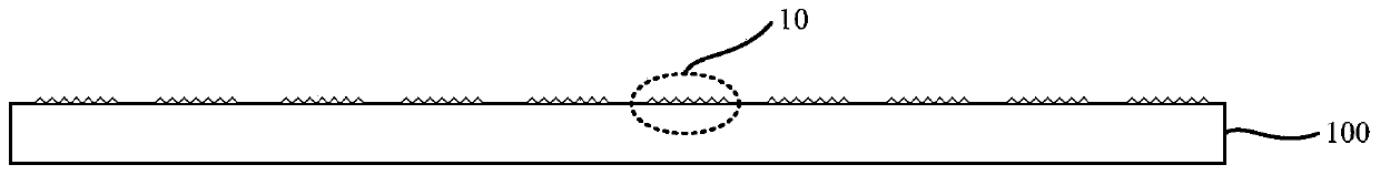
[0041] like figure 1 and Figure 4 As shown, in the light guide plate 100 according to an embodiment of the present invention, a plurality of blazed gratings 10 are arranged on the light emitting s...


PUM


Abstract

The invention relates to a light guiding plate, a backlight module and a display device, wherein a plurality of blazed gratings are arranged on a light-exiting surface of the light guiding plate, each blazed grating comprises a plurality of projections, each projection comprises a first groove surface and a second groove surface, each first groove surface is used for adjusting the existing direction of light so as to enable existed light to intersect at a first point, and each second groove surface is used for adjusting the existing direction of light so as to enable existed light to intersect at a second point. According to the embodiments of the invention, two light sources can be set for the light guiding plate, the two light sources are started in a time sharing manner, and when one eye of an observer is arranged at the first point and the other eye is arranged at the second point, the double eyes can respectively receive an image formed by the light of the first groove surface and an image formed by the light of the second groove surface, so that the observer is enabled to see a 3D frame.

Description

technical field [0001] The present invention relates to the field of display technology, in particular to a light guide plate, a backlight module and a display device. Background technique [0002] In recent years, 3D technology has developed rapidly. Glasses-free 3D display has attracted more attention than glasses-based 3D technology because it does not require wearing glasses. At present, the main glasses-free 3D technologies can be divided into: [0003] 1. Directional backlight; [0004] 2. Parallax barrier type; [0005] 3. Cylindrical lens array. [0006] Among them, the directional backlight type requires time-division multiplexing of light sources, the technology is more complicated and there is a loss of resolution when viewing in 3D; [0007] The transmittance of the parallax barrier is lower than 50%, and the cost is high, the volume is large, and the weight is heavy, which is not conducive to commercial promotion; [0008] Compared with the parallax barrie...

Claims


Application Information

Patent Timeline
Patent Type & Authority Patents(China)
IPC IPC(8): G02B27/22G02B6/00
CPCG02B6/005G02B6/0068G02B30/27
Inventor 高健陈小川赵文卿
Owner BOE TECH GRP CO LTD
Features
  • R&D
  • Intellectual Property
  • Life Sciences
  • Materials
  • Tech Scout
  • Unparalleled Data Quality
  • Higher Quality Content
  • 60% Fewer Hallucinations
Learn More