Linear vibration motor

A technology of linear vibration and vibration system, applied in the direction of electromechanical devices, electrical components, etc., can solve the problems of affecting the stability of vibration motor performance, easy to generate splashes, and difficult to fix the magnetic fluid.

Active Publication Date: 2016-06-15
GOERTEK INC
View PDF5 Cites 15 Cited by
  • Summary
  • Abstract
  • Description
  • Claims
  • Application Information

AI Technical Summary

Problems solved by technology

[0007] In view of the above problems, the purpose of the present invention is to provide a linear vibration motor to solve the problems that the current vibration motor uses magnetic fluid to reduce noise. The magnetic fluid is not easy to fix, and it is easy to generate splashes, which affects the performance stability of the vibration motor.

Method used


Image

  • Linear vibration motor
  • Linear vibration motor

Examples


Embodiment 1

[0034] Embodiment 1 (the fixed part of the elastic support is fixedly connected with the lower shell, and the sliding part and the mass block slide and rub)

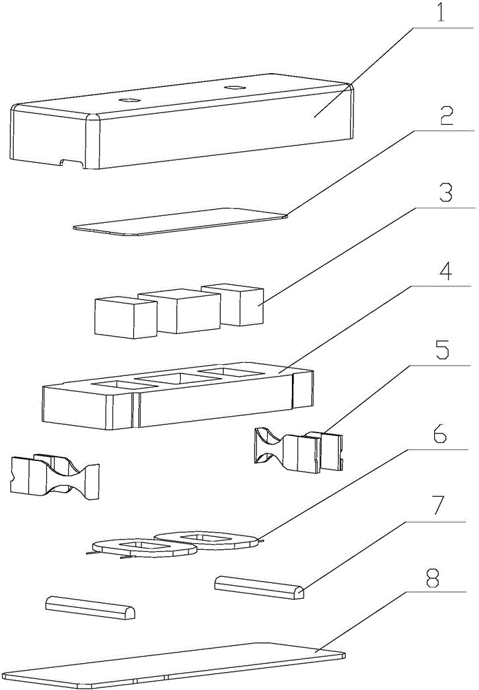
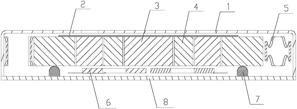
[0035] In the first embodiment, the shell includes an upper shell 1 provided with a notch, and a lower shell 8 which is fitly connected with the upper shell 1 and forms a cavity, and the vibration system and the stator are accommodated in the cavity. Wherein, the lower case 8 is made of a magnetically permeable material, and can generate a mutual attracting magnetic force with the permanent magnet 3 . The elastic support 7 is a strip-shaped structure, and two elastic supports 7 are symmetrically fixed on both sides of the stator and kept a certain distance therefrom, and the elastic support 7 is located on the same side of the mass block 4. The other side of the mass block 4 is provided with a magnetically permeable plate 2 , and the magnetically permeable plate 2 is pasted on the side of the mass block 4 by pasting or w...

Embodiment 2

[0038] Embodiment 2 (the fixed part of the elastic support is fixedly connected with the mass block, and the sliding part and the lower shell slide and rub)

[0039] In the second embodiment, the structures of the casing, the spring member, the magnetically conductive plate and the elastic support member can all refer to the description in the first embodiment, and will not be repeated here. In the second embodiment, the elastic support is located on the same side of the mass block, and the fixed part of the elastic support is fixedly connected with the mass block, and moves with the movement of the mass block, and the sliding part of the elastic support is in contact with the lower mass block. shell sliding contact.

[0040] Wherein, the two ends of the mass block are respectively elastically connected to the side wall of the upper case through the spring parts, and the elastic restoring force is provided for the movement of the mass block through the spring parts. During the...


PUM


Abstract

The invention provides a linear vibration motor, which comprises an upper shell, a lower shell, a vibration system, a stator and a spring piece, wherein the upper shell and the lower shell are in fit connection; the vibration system is suspended in the upper shell and the lower shell; the stator is arranged corresponding to the vibration system; the spring piece supports the vibration system and provides an elastic recovery force for the vibration system; the vibration system comprises a mass block and a permanent magnet combined in the middle position of the mass block; a magnetic material is punched to form the lower shell; an elastic support piece is arranged between the mass block and the lower shell; and the elastic support piece is fixed on the mass block / lower shell and performs sliding friction with the lower shell / mass block when the mass block moves. Thus, the frequency band width of the linear vibration motor can be expanded, and collision and noise are reduced.

Description

technical field [0001] The invention relates to the technical field of consumer electronics, and more specifically, relates to a linear vibration motor applied to portable consumer electronics products. Background technique [0002] With the development of communication technology, portable electronic products, such as mobile phones, handheld game consoles or handheld multimedia entertainment devices, have entered people's lives. In these portable electronic products, micro-vibration motors are generally used for system feedback, such as incoming call prompts for mobile phones, vibration feedback for game consoles, etc. However, with the continuous development and wide application of electronic products, higher and higher requirements are placed on the performance and service life of the vibration motor. [0003] Existing vibration motors generally include an upper cover, a lower cover forming a vibration space with the upper cover, a vibrator (including a mass and a perman...

Claims


Application Information

Patent Timeline
Patent Type & Authority Applications(China)
IPC IPC(8): H02K33/02
CPCH02K33/02
Inventor 孙野孙长军
Owner GOERTEK INC
Why Eureka
Try Eureka