
Blow molding device

A technology of blow molding and preforms, applied in the direction of household components, applications, household appliances, etc., to achieve the effect of improving straightness

Active Publication Date: 2016-06-15
DISCMA
View PDF5 Cites 0 Cited by
  • Summary
  • Abstract
  • Description
  • Claims
  • Application Information

AI Technical Summary

Problems solved by technology

However, it is difficult to stretch the preform straight in the longitudinal direction only by the pressurization of the liquid filling, and the preform cannot be blow-molded stably due to eccentricity and cracking.

Method used


Image

  • Blow molding device
  • Blow molding device
  • Blow molding device

Examples


Embodiment Construction

[0030] Hereinafter, embodiments of the present invention will be illustrated and described in detail with reference to the drawings.

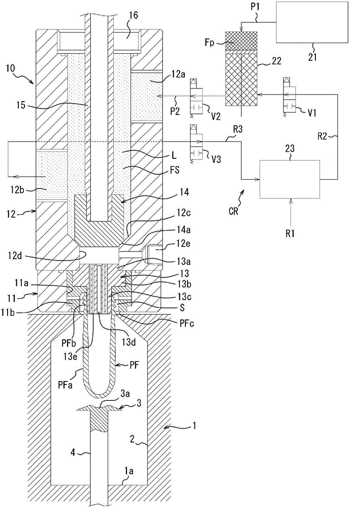
[0031] figure 1 The shown blow molding apparatus as one embodiment of the present invention has a mold 1 for blow molding. The cavity 2 of the mold 1 has an altar shape and opens upward on the upper surface of the mold 1 . Details are not shown, but the mold 1 can be opened left and right, and the molded product can be taken out from the mold 1 by opening the mold 1 .

[0032] A welcoming member (welcoming member) 3 is provided on the die 1 . The receiving member 3 is formed into a disc shape having a mountain-shaped cross-sectional shape with a concave portion 3 a on the central upper surface, and is supported by a support shaft 4 protruding from the center position of the bottom surface 1 a of the mold 1 and arranged in the cavity 2 of the mold 1 . Inside. The support shaft 4 is supported by the mold 1 so as to be movable vertically. Acc...


PUM


Abstract

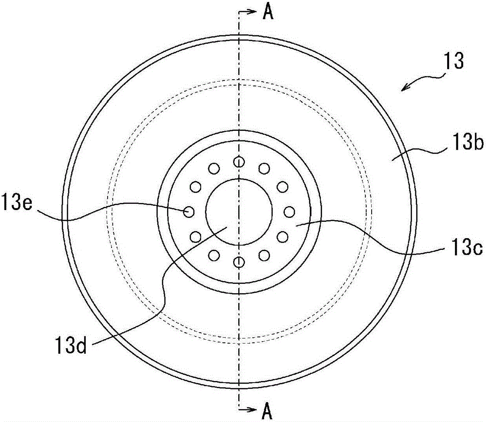
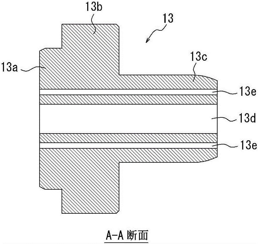
A blow molding device which: comprises a blow molding mold (1) in which a bottomed cylindrical preform (PF) is fitted, a blow nozzle (13) that is fitted together with the mouth tube section (PFb) of the preform (PF) fitted in the mold (1), and a pressurized liquid-supplying unit (22) for supplying a pressurized liquid (L) to the blow nozzle (13); and molds the preform (PF) into the shape that conforms to the cavity (2) of the mold (1) by filling the liquid (L) into the preform (PF) through the blow nozzle (13). The blow nozzle (13) is characterized in: having a central hole (13d) disposed at the shaft center thereof and multiple peripheral holes (13e) formed to have smaller internal diameters than the central hole (13d) and disposed so as to surround the central hole (13d); and the liquid (L) being filled through the central hole (13d) and the multiple peripheral holes (13e) into the preform (PF).

Description

technical field [0001] The present invention relates to a blow molding device for blow molding a bottomed cylindrical preform into a pot, and more particularly to a blow molding device for using a liquid as a pressurized fluid for blow molding. Background technique [0002] Resin jars such as jars made of stretched polypropylene (OPP) and jars made of polyethylene terephthalate (PET) (polyester bottles) are being used for beverages, Various uses such as food and cosmetics. Such an altar is usually formed into a predetermined shape by biaxial stretch blow molding of a resin preform formed into a bottomed cylindrical shape by injection molding or the like using a blow molding device. [0003] As a blow molding device, there is known a device that uses a pressurized liquid instead of pressurized air as the pressurized fluid filled in the preform. In this case, by using the content liquid that is finally filled into the product, such as beverages, cosmetics, and medicines, as ...

Claims


Application Information

Patent Timeline
IPC IPC(8): B29C49/60B29C49/46
CPCB29C49/06B29C49/14B29C49/16B29C49/085B29C49/58B29C2049/4664B29K2023/06B29K2023/12B29K2067/003B29L2031/7158B29C49/087B29C2949/0715B29C49/46B29C49/30B29K2105/258
Inventor 田端真一森上茂树盐川满
Owner DISCMA
Learn More