Supercharge Your Innovation With Domain-Expert AI Agents!

A medical apparatus data collection system and a configuration method therefor

A technology of data acquisition system and medical equipment, applied in radiological diagnostic image/data processing, medical science, instruments for radiological diagnosis, etc., can solve the problems of poor reliability, multiple layers, high system cost, etc., and achieve the goal of improving adaptability Effect

Active Publication Date: 2016-06-22
SHANGHAI UNITED IMAGING HEALTHCARE
View PDF6 Cites 5 Cited by
  • Summary
  • Abstract
  • Description
  • Claims
  • Application Information

AI Technical Summary

Problems solved by technology

It can be seen that the detection component 110 and the detector interface circuit board 120 adopt an end-to-end approach, which leads to more levels of collection, complex systems, higher system costs, and poor reliability.

Method used


Image

  • A medical apparatus data collection system and a configuration method therefor
  • A medical apparatus data collection system and a configuration method therefor
  • A medical apparatus data collection system and a configuration method therefor

Examples


Embodiment 1

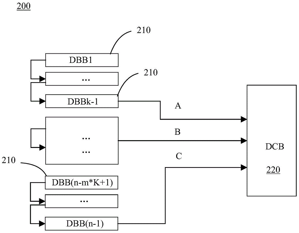
[0026] figure 2 It is the structure of the data acquisition system according to an embodiment of the present invention. refer to figure 2 As shown, the system 200 of this embodiment includes a plurality of detection components 210 (n−1 are shown in the figure) and a data collection circuit board 220 . A plurality of detection components 210 are connected in a serial-parallel hybrid manner, thus forming a plurality of channels A, B and C. Each channel A, B, and C is connected in parallel to the data collection circuit board 220, and within each channel, the detection components are connected in series. Each channel has one and only one detection assembly directly connected to the data collection circuit board 220 . It can be understood that the number m of channels varies here, and the corresponding number k of detection components of each channel also varies. For example, the number m of channels is 2 or more, and the number of detection components k of each channel is 1...

Embodiment 2

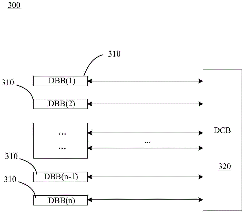
[0040] image 3 is the structure of a data acquisition system according to another embodiment of the present invention. refer to image 3 As shown, the system 300 of this embodiment includes a plurality of detection components 310 and a data collection circuit board 320 . A plurality of detection components 310 are connected in parallel, thus forming n channels (n is the number of detection components), which are respectively connected to the data collection circuit board 220 . There is one and only one detection assembly 310 per channel, which is directly connected to the data collection circuit board 320 .

[0041] Here, the data collection circuit board 320 is configured to identify the channels through which each detection assembly 310 is connected to the data collection circuit board 320 according to the pins that are physically connected. For example, by directly connecting to the detection components DBB(1), DBB(2) and DBB(n) of the data collection circuit board 320,...


PUM


Abstract

The invention provides a medical apparatus data collection system and a configuration method therefor. The data collection system comprises a data collection circuit board and a plurality of detection assemblies connected in parallel, in series or in parallel and in series. The data collection circuit board is connected to the detection assemblies, wherein one or multiple detection assemblies connected to the data collection circuit board directly form a channel. The data collection circuit board is configured to identify a channel of connection from each detection assembly to the data collection circuit board according to pins of physical connection, send a command of configuring identification numbers to the detection assemblies of each channel, and calculate identification numbers according to the channel position numbers fed back by the detection assemblies of the channels and configure the identification numbers to the detection assemblies of the channels. The detection assemblies are configured to determine the channel position numbers according to the command and feed the channel position numbers back to the data collection circuit board.

Description

technical field [0001] The present invention mainly relates to the field of medical equipment, in particular to a data collection system of medical equipment and a configuration method thereof. Background technique [0002] Medical equipment, especially large medical equipment such as computed tomography (Computed Tomography, CT) equipment, magnetic resonance imaging (Magnetic Resonance Imaging, MRI) equipment, and X-ray equipment, use detectors to detect signals for subsequent imaging. Take CT equipment as an example, which contains X-ray detectors. This X-ray detector has as many as tens of thousands to hundreds of thousands of sensing units (pixels). Due to chip integration, channel bandwidth and heat dissipation, these sensing units form up to dozens of detection components (DBB) . [0003] The traditional detector management system (Detector Management system, DMS) transmits data one by one for each detection unit of the detector, merges the data on the back-end detec...

Claims


Application Information

Patent Timeline
IPC IPC(8): A61B5/055A61B6/03A61B6/00
CPCA61B5/055A61B5/72A61B6/00A61B6/03A61B6/52
Inventor 杨隆梓
Owner SHANGHAI UNITED IMAGING HEALTHCARE
Features
  • R&D
  • Intellectual Property
  • Life Sciences
  • Materials
  • Tech Scout
  • Unparalleled Data Quality
  • Higher Quality Content
  • 60% Fewer Hallucinations
Learn More