
Dust removal filtering device and method

A technology of filtering device and filtering method, which is applied in separation methods, dispersed particle filtering, chemical instruments and methods, etc., can solve the problems of blockage of filter elements, high filtering pressure difference, poor filter recoil regeneration effect, etc. The effect of reducing maintenance cost, avoiding secondary dust and reducing load

Active Publication Date: 2016-06-22
SHANGHAI LANKE PETROCHEM ENG & TECH
View PDF8 Cites 1 Cited by
  • Summary
  • Abstract
  • Description
  • Claims
  • Application Information

AI Technical Summary

Problems solved by technology

However, there are still shortcomings in the existing dust removal device, because most manufacturers adopt the way of air intake from the bottom of the filter, that is, the air intake direction of the gas to be filtered is from bottom to top, which will cause the filter to rely on The falling dust filter cake is easily broken up by the rising gas to be filtered, and forms secondary dust with the rising of the gas to be filtered, and the rising dust particles quickly return to the filter element to form a filter cake, thus causing the filter Poor backflush regeneration effect, high filter pressure difference, frequent backflush and large air consumption can also lead to clogging of filter elements

Method used


Image

  • Dust removal filtering device and method

Examples


Embodiment 1

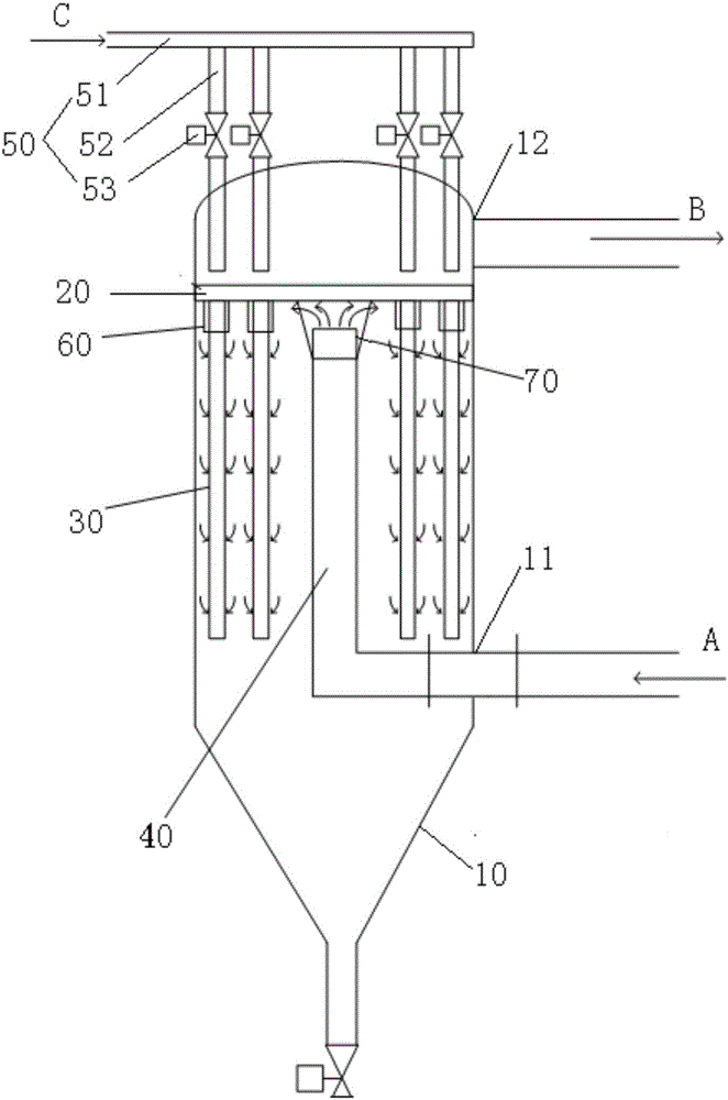
[0033] Embodiment 1 discloses a dust removal and filtering device, comprising: a casing, an air inlet and an air outlet are arranged on the casing, the air inlet is arranged at the lower end of the casing, and the air outlet is arranged at the upper end of the casing; A plate, the tube plate is provided with at least one through hole, the tube plate is arranged inside the shell, and is located between the air inlet and the air outlet of the shell; at least one filter element, the filter element is arranged inside the shell and is located Below the through hole of the tube sheet, its upper end is fixed on the tube sheet; the air intake pipe extends through the air inlet of the shell to the inside of the shell, and the air outlet of the air intake pipe is located below the tube plate; The blowing structure and the back blowing structure are arranged above the tube sheet, and the air outlet direction of the back blowing structure faces the through hole of the tube sheet.

[0034]...

Embodiment 2

[0037] Compared with embodiment one, the improvement of embodiment two is that the blowback structure in the dust removal and filtering device disclosed in embodiment two includes a main pipeline and a plurality of sub-pipes, and the sub-pipes are fixed on the main pipeline and connected with the main pipeline Each sub-pipe has a blowing port, the blowing port faces the through hole on the tube plate, and each sub-pipe is provided with a valve. Specifically, a filter element is correspondingly provided below each blowing port of the sub-pipe.

[0038] The subpipes in the backflushing structure of the dust removal filter device in this embodiment are correspondingly provided with a filter element, and a subpipe and its corresponding filter element are a partition, and when backflushing is required, only one partition can be backflushed , it is also possible to perform back-flushing on a plurality of partitions, which can effectively improve the application flexibility of the dust...

Embodiment 3

[0041] Compared with the first embodiment, the improvement of the third embodiment is that the dust removal and filtering device disclosed in the third embodiment also includes: a plurality of wear-resistant sleeves, the wear-resistant sleeves are set on the filter element, and are located on the filter element upper end.

[0042] Specifically, the height of the anti-wear sleeve is equal to the distance between the upper end surface of the intake pipe and the lower end surface of the tube sheet; the inner diameter of the anti-wear sleeve is 2 to 5 mm larger than the outer diameter of the filter element; The blue connection is fixed on the tube plate, which can effectively improve the installation stability of the anti-wear sleeve and further improve its protection effect on the filter element.

[0043] Due to the high flow rate and high dust concentration of the gas to be filtered at the air outlet of the intake pipe, the upper end of the filter element near the intake pipe is...


PUM


Abstract

The invention discloses a dust removal filtering device and method. The dust removal filtering device comprises a shell, a tubular plate, at least one filtering element, an air inlet pipeline and a back flushing structure, wherein the shell is provided with an air inlet and an air outlet, the air inlet is formed in the lower end of the shell, and the air outlet is formed in the upper end of the shell; the tubular plate is provided with at least one through hole, arranged in the shell and located between the air inlet and the air outlet of the shell; the filtering element is arranged in the shell and located below the through hole of the tubular plate, and the upper end of the filtering element is fixed to the tubular plate; the air inlet pipeline penetrates through the air inlet of the shell and extends into the shell, and the air outlet of the air inlet pipeline is located below the tubular plate; the back flushing structure is arranged below the tubular plate, and the air outlet direction of the back flushing structure faces the through hole of the tubular plate. The dust removal filtering device is simple and reasonable in structure, the load of the filtering element can be effectively reduced, the reentrainment problem is effectively avoided in the back flushing process, dust removal efficiency of the dust removal filtering device is improved, and cost is reduced.

Description

technical field [0001] The invention relates to the technical field of dust removal and filtration structure and method design, in particular to a dust removal and filtration device and method. Background technique [0002] At present, more and more dust removal devices tend to adopt a continuous online regenerative dust removal system. The specific form is that all filter elements are installed in a large filter housing and divided into several partitions, which are connected to each other. And each partition is equipped with a separate back-flushing pipeline. When the filter needs to be back-flushed and regenerated, only one partition is back-flushed, and the other partitions are dust-removed and filtered, thereby achieving simultaneous filtering and back-flushing. [0003] Compared with the traditional multi-chamber dust removal system, the advantages of the existing dust removal device are that the floor area and the number of equipment valves are greatly reduced, and th...

Claims


Application Information

Patent Timeline
Patent Type & Authority Applications(China)
IPC IPC(8): B01D46/00
CPCB01D46/0005B01D46/58B01D46/71
Inventor 朱洪周航马洪玺张文军
Owner SHANGHAI LANKE PETROCHEM ENG & TECH
Learn More