A hydrogen production process method and system

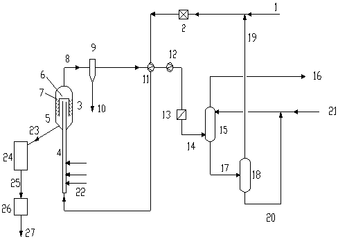
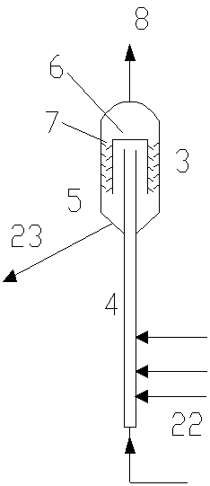
A process method and technology of a pyrolysis reactor are applied in the field of hydrogen production in the process of acid gas treatment, which can solve the problems of low decomposition rate and low hydrogen equilibrium concentration, and achieve the advantages of improving conversion rate, realizing gas-solid separation, and reducing processing load. Effect

Active Publication Date: 2018-10-12
CHINA PETROLEUM & CHEM CORP +1
View PDF7 Cites 0 Cited by
  • Summary
  • Abstract
  • Description
  • Claims
  • Application Information

AI Technical Summary

Problems solved by technology

h 2 The catalytic thermal decomposition of S refers to the H 2 S gas undergoes thermal decomposition reaction on transition metal sulfides, but due to the influence of chemical equilibrium, H 2 The decomposition rate of S is low, so the equilibrium concentration of hydrogen in the system is low; H 2 The direct thermal decomposition of S is the thermal cracking of H under non-catalytic conditions 2 S is decomposed into S and H 2 , due to H 2 The decomposition of S into elemental sulfur and hydrogen requires endothermic reaction, which is a thermodynamically unfavorable reaction, and only at very high temperatures has a higher decomposition rate. According to literature reports, in order to make H 2 S obtains a decomposition rate of more than 50% through direct thermal decomposition, and the reaction temperature must exceed 1658K; the superadiabatic decomposition method is H 2 S in the absence of catalyst and external heat source, using porous media superadiabatic combustion technology to realize H 2 S decomposition, this technology due to the introduction of air for combustion, makes H 2 S in H 2 not fully recycled

Method used


Image

  • A hydrogen production process method and system
  • A hydrogen production process method and system

Examples


Embodiment 1

[0049] Treat raw gas H 2 S concentration 100%, flow 4000Nm 3 / h; the particle size of Fe powder is 1-3mm, and the Fe powder is preheated to 800°C before entering the reactor; the absorption tower uses N-methyldiethanolamine as the absorbent. After the feed gas passes through the pyrolysis reactor, H 2 S generates H 2 The conversion rate is 31%, and the absorption tower top gas flow rate is 1235Nm 3 / h, H 2 The purity is 100%.

Embodiment 2

[0051] Treat raw gas H 2 The S concentration is 100%, the flow rate is 4000Nm3 / h; the Fe powder particle size is 1-3mm, and the Fe powder is preheated to 900°C before entering the reactor; the absorption tower uses N-methyldiethanolamine as the absorbent. After the feed gas passes through the pyrolysis reactor, H 2 S generates H 2 The conversion rate is 37%, and the absorption tower top gas flow rate is 1450Nm 3 / h, H 2 The purity is 100%.

Embodiment 3

[0053] Treat raw gas H 2 The concentration of S is 100%, the flow rate is 4000Nm3 / h; the particle size of Fe powder is 1-3mm, and the Fe powder is preheated to 1000°C before entering the reactor; the absorption tower uses N-methyldiethanolamine as the absorbent. After the feed gas passes through the pyrolysis reactor, H 2 S generates H 2 The conversion rate is 45%, and the absorption tower top gas flow rate is 1780Nm 3 / h, H 2 The purity is 100%.


PUM

PropertyMeasurementUnit
angleaaaaaaaaaa
particle diameteraaaaaaaaaa

Abstract

The invention provides a hydrogen production process method. According to the hydrogen production process method, raw material gas enters a pyrolysis reactor and is subjected to a reaction in the presence of iron powder, the reaction effluent is separated to obtain a gas phase material and a solid phase material, the gas phase material is recovered by a sulfur collector to obtain elemental sulfur, the obtained gas phase material enters desulfurization equipment and reacts with an absorbent to obtain a hydrogen-rich gas and a rich absorption liquid, the rich absorption liquid enters a regeneration tower to obtain a regenerated absorbent and desorption gas, and the solid phase material enters a magnetic field separator and is separated t obtain ferrous sulfide and iron powder. The present invention further provides a hydrogen production process system. With the method and the system f the present invention, the H2S decomposition rate can be improved.

Description

technical field [0001] The invention relates to the technical field of environmental protection, in particular to a new technology for producing hydrogen in the acid gas treatment process. Background technique [0002] Hydrogen sulfide is a toxic gas that pollutes the environment and widely exists in oil and gas exploration, petrochemical, coal chemical and other industries. It must be recycled during the production process. [0003] There are two main methods for the recovery and treatment of hydrogen sulfide in the industry, namely the Claus method and the wet absorption method: the Claus method mainly converts H 2 S is converted into elemental sulfur and water through partial incomplete oxidation and exchange reaction; the wet absorption process is a method of directly oxidizing H with an oxidant in the liquid phase. 2 S method. The disadvantages of these two types of sulfur recovery methods are that the process consumes a lot of energy and the hydrogen has not been rec...

Claims


Application Information

Patent Timeline
Patent Type & Authority Patents(China)
IPC IPC(8): C01B3/04
CPCY02E60/36
Inventor 王阳峰张英薄德臣张伟郭土高明胡丞
Owner CHINA PETROLEUM & CHEM CORP
Why Eureka
Try Eureka