One-time stamping forming mold for ball pocket of holder

A stamping forming and cage technology, which is applied to the field of one-step stamping and forming molds for cage ball pockets, can solve the problems of difficulty in meeting technical standard requirements, large errors in the circumferential spacing of pockets, and easy distortion and deformation, and achieves uniform force, The effect of reducing axial position error and increasing punch strength

Active Publication Date: 2016-06-22
ZHEJIANG GUNAI RUBBER & PLASTIC SCI & TECH
View PDF4 Cites 6 Cited by
  • Summary
  • Abstract
  • Description
  • Claims
  • Application Information

AI Technical Summary

Problems solved by technology

[0003] A few days ago, for the ball cage cage, because the inner and outer diameters of the cage are spherical, and the pockets are spherical pockets, it is difficult to process spherical pockets on the spherical arc surface, and the general conventional technology is difficult to meet the technical standards.
The traditional processing technology is generally to first mark the position of the pockets on the cage through calculation, and then use the corresponding die to punch out the individual pockets one by one. The structure of the die is simple, but there are problems when marking the positions of the pockets. Large errors lead to large errors in the circumferential spacing between the pockets and low axial position accuracy; in addition, punching one by one will cause uneven force on the cage, prone to distortion and deformation, and cause serious hidden dangers , so that it is difficult to install the roller, and it is easy to appear the phenomenon of inflexible rotation

Method used


Image

  • One-time stamping forming mold for ball pocket of holder
  • One-time stamping forming mold for ball pocket of holder
  • One-time stamping forming mold for ball pocket of holder

Examples


Embodiment 1

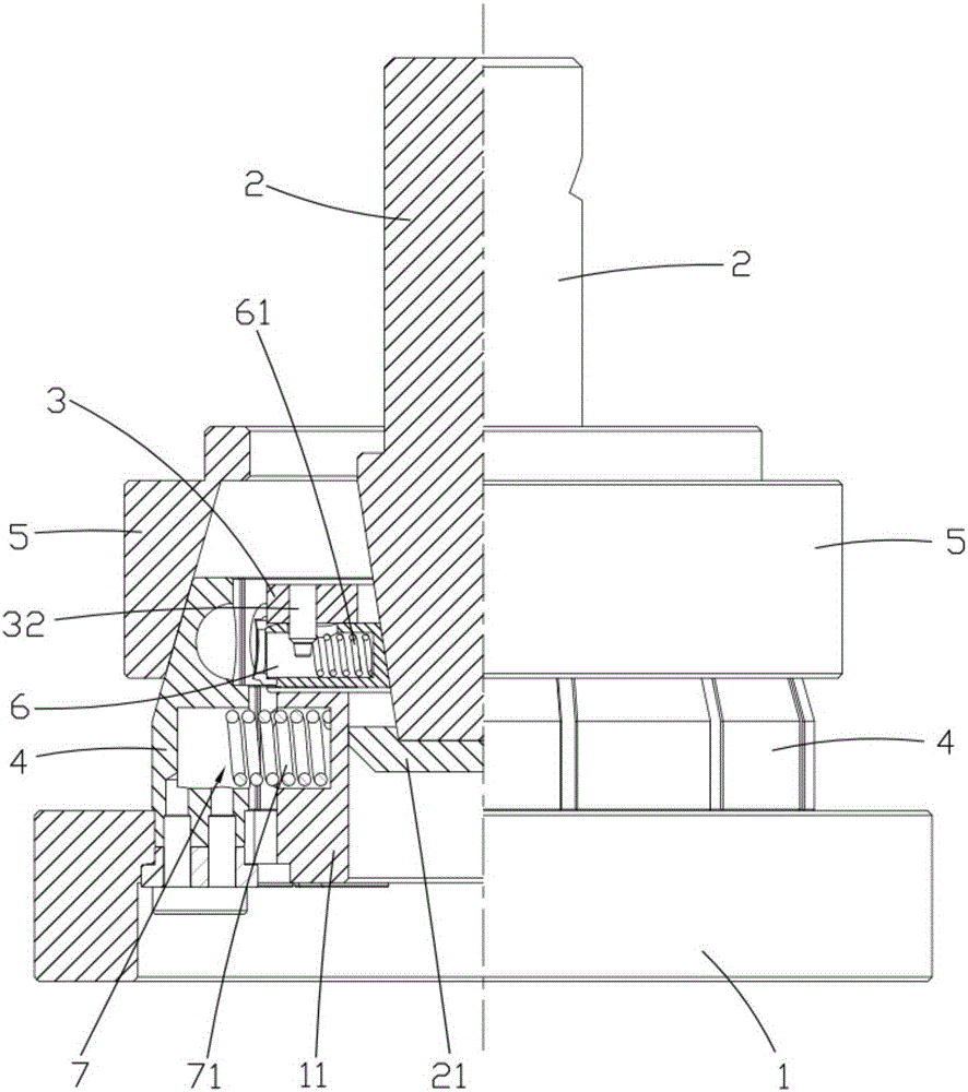
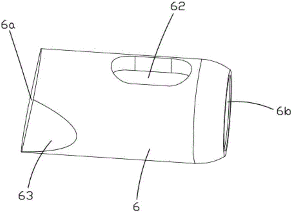
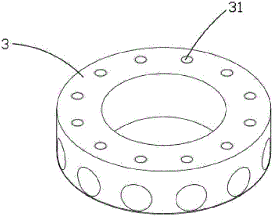
[0030] Such as figure 1 As shown, the present invention provides a one-time stamping mold for a cage ball pocket, including a base 1, a main slider 2, an inner mold 3, an outer mold 4, a shrink sleeve 5 and several elastic recovery mechanisms 7, the base 1, The main sliding body 2, the inner mold 3, the outer mold 4 and the shrink sleeve 5 are arranged coaxially. The main sliding body 2 is in the shape of an inverted cone, which is placed vertically in the base 1. The inner mold 3 is sleeved on the main sliding body 2. Outside; the base 1 is evenly distributed with several outer molds 4 along its circumference, and the outer molds 4 are all placed outside the inner mold 3, and the upper part of the outer mold 4 is covered with a shrink sleeve 5; the side wall of the inner mold 3 is along the Several punches 6 are evenly arranged in its circumferential direction, and the inner end surface 6a of the punch 6 is in conflict with the main sliding body 2, and the inner wall of the o...


PUM


Abstract

The invention relates to a one-time stamping forming mold for a ball pocket of a holder. The one-time stamping forming mold comprises a base, a main sliding body, an inner mold, outer molds and a shrink sleeve. The main sliding body is arranged inside the base vertically; the main sliding body is sleeved with the inner mold, and a plurality of outer molds are evenly arranged on the base in the circumferential direction; the outer molds are all arranged outside the inner mold; the shrink sleeve is arranged on the upper portions of the outer molds in a sleeving mode; a plurality of punches are evenly arranged on the side wall of the inner mold in the circumferential direction; and limiting grooves are formed in the inner walls of the outer molds. A first spring is placed horizontally inside each punch; a kidney-shaped hole is formed in the upper portion of each punch; a plurality of pin holes are evenly formed in the upper end face of the inner mold; and a plug pin is arranged inside each pin hole. According to the one-time stamping forming mold for the ball pocket of the holder, the diameter variation of the main sliding body is utilized to push the punches to move radially in a divergent way along the main sliding body, so that multiple holes are punched in the ball pocket of the holder at a time; through the elastic effect of the first springs arranged inside the punches, automatic resetting of the punches after the completion of the punching is achieved. The mold is simple, punching is stable and highly precise, and automation and flow line operation can be easily achieved.

Description

technical field [0001] The invention relates to the field of molds, in particular to a one-time stamping mold for ball pockets of cages. Background technique [0002] As we all know, bearings generally include four parts: outer ring, inner ring, rolling body and cage. Among them, the cage refers to the bearing parts that partially wrap all or part of the rolling body and move with it to isolate the rolling body and prevent rolling. The rolling elements are brought together and usually guide the rolling elements and keep them in the bearing. The accuracy and quality of the cage in the bearing will affect the rolling condition of the rollers and the bearing clearance, which will directly affect the performance of the bearing. As the mold is the direct equipment for producing the cage, it is particularly important to design a reasonable mold structure. [0003] A few days ago, for the ball cage cage, because the inner and outer diameters of the cage are spherical, and the pock...

Claims


Application Information

Patent Timeline
Patent Type & Authority Applications(China)
IPC IPC(8): B21D53/12B21D28/34
CPCB21D28/34B21D53/12
Inventor 陈仁波胡乃达李学中刘宗勇刘荣格刘校辉许磊
Owner ZHEJIANG GUNAI RUBBER & PLASTIC SCI & TECH
Why Eureka
Try Eureka