Mat splitting machine

A cutting machine and floor mat technology, applied in the field of floor mat manufacturing, can solve the problems of rough cutting surface, low cutting efficiency, easy to cause damage, etc., and achieve smooth cutting surface without burrs, adjustable cutting width, and automation high degree of effect

Active Publication Date: 2016-06-22
ZHEJIANG RUNYANG NEW MATERIAL TECH
View PDF6 Cites 7 Cited by
  • Summary
  • Abstract
  • Description
  • Claims
  • Application Information

AI Technical Summary

Problems solved by technology

[0002] At present, a variety of floor mats are widely used. In addition to the traditional laying of floors in offices and lobbies, they can also be used as a base film for laying floors. These floor mats are usually made of foam materials and have A variety of different specifications and sizes need to be slit on demand during production. However, traditional slitters have disadvantages such as low slitting efficiency and poor slitting effect on foam materials.
[0003] For example, the gantry-type large-diameter paper slitting machine disclosed in CN104891248A performs slitting by unwinding and rewinding. The efficiency of this kind of slitting is low, and a lot of time is wasted in the rewinding and unwinding process, which seriously affects production efficiency.
As another example, CN204431333U discloses a kind of fully automatic paper cutting tube machine, which adopts a rotating cutter to cut, but the cutting width of this kind of cutting machine is small, it is difficult to be suitable for the floor mat production of a large plate, and the rotating cutter has a great impact on foaming. The cutting effect of the material is poor, the cutting surface is not smooth, and it is easy to cause damage

Method used


Image

  • Mat splitting machine
  • Mat splitting machine
  • Mat splitting machine

Examples


Embodiment 1

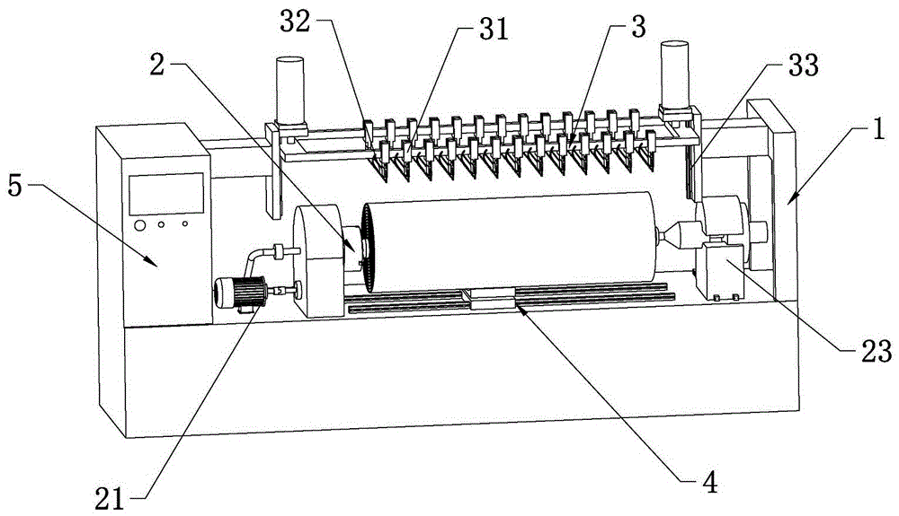
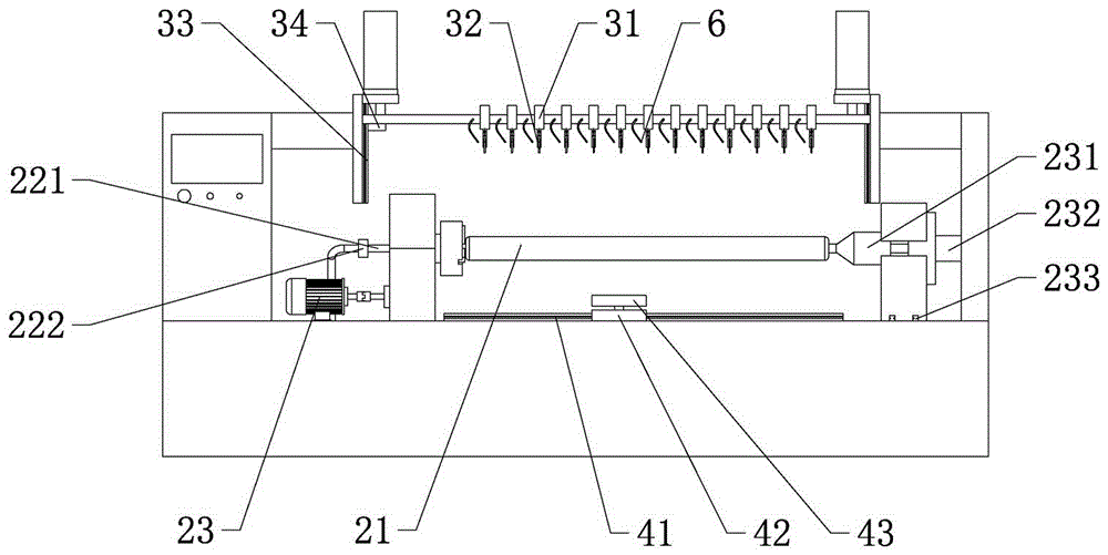
[0029] according to Figure 1 ~ Figure 3 As shown, a floor mat cutting machine includes: a frame 1, a rotating device 2 for driving materials, a cutting table 3 for cutting materials, a feeding device 4 for upper and lower materials, and coordinated control of the operation of each device The control mechanism 5; the rotating device 2 includes a driver 21 fixed on the frame 1, a rotating shaft 22 connected to the driver 21 and a positioning mechanism 23 for supporting and positioning the rotating shaft 22; the cutting table 3 is provided with a plurality of cutting parts Fixed frame 31, cutting piece fixed frame 31 is provided with strip blade 32, and cutting piece fixed frame 31 and blade 32 joints are also provided with tension adjustment mechanism, thereby ensure the degree of tension of blade 32, cutting piece fixed frame 31 Adjustable connection with the cutting table 3, so that the distance between the blades 32 can be adjusted, a sliding mechanism 33 is provided between...

Embodiment 2

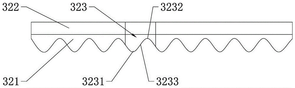
[0035] The difference from the above-mentioned embodiment 1 is that, according to Figure 4 As shown, the size of each cutting unit 323 is different, and the cutting unit 323 located in the middle section of the blade area 321 is smaller in size than the cutting units 323 on both sides of the blade area 321 and arranged more closely. For roll-shaped materials, under the same amount of feed, the blade area facing the center of the circle will bear more cutting volume. By setting up a tighter cutting unit 323 in the middle section of the blade area 321, the cutting efficiency can be effectively improved, and Extend tool life.

Embodiment 3

[0037] The difference from the above-mentioned embodiment 1 is that, according to figure 2 As shown, the cutting table 3 is provided with a distance sensor 34 for controlling the stroke of the cutting table 3 to further control the movement range of the cutting table 3 so as to ensure the cutting amount.


PUM


Abstract

The invention relates to the field of mat manufacturing, in particular to a mat splitting machine. The mat splitting machine comprises a machine frame, a rotary device used for driving materials, a cutting platform used for splitting the materials, a conveying device used for feeding and discharging the materials and a control mechanism used for controlling all the devices to operate coordinately. The rotary device comprises a driver fixed to the machine frame, a rotary shaft connected with the driver and a positioning mechanism used for supporting and positioning the rotary shaft. The cutting platform is provided with a plurality of cutter fixing frames provided with long-strip-shaped cutters, and the cutter fixing frames and the cutting platform are adjustably connected, so that the distance between the cutters is adjustable. A sliding mechanism is arranged between the cutting platform and the machine frame, and the cutting platform moves far away from or close to the rotary shaft through the sliding mechanism.

Description

technical field [0001] The invention relates to the field of floor mat manufacturing, in particular to a floor mat cutting machine. Background technique [0002] At present, a variety of floor mats are widely used. In addition to the traditional laying of floors in offices and lobbies, they can also be used as a base film for laying floors. These floor mats are usually made of foam materials and have A variety of different specifications and sizes need to be cut on demand during production. However, traditional slitting machines have disadvantages such as low cutting efficiency and poor cutting effect on foam materials. [0003] For example, the gantry-type large-diameter paper slitting machine disclosed in CN104891248A performs slitting by unwinding and rewinding. The efficiency of this kind of slitting is low, and a lot of time is wasted in the rewinding and unwinding process, which seriously affects production efficiency. . As another example, CN204431333U discloses a k...

Claims


Application Information

Patent Timeline
Patent Type & Authority Applications(China)
IPC IPC(8): B26D1/52B26D7/06B26D7/08B26D5/00
CPCB26D1/525B26D5/00B26D7/06B26D7/08
Inventor 张镤
Owner ZHEJIANG RUNYANG NEW MATERIAL TECH
Why Eureka
Try Eureka