A floor mat cutting machine
A slitting machine and floor mat technology, applied in the field of floor mat manufacturing, can solve the problems of uneven cutting surface, low cutting efficiency, easy to produce damage, etc., and achieve smooth cutting surface without burrs, adjustable slitting width, automatic high degree of effect
- Summary
- Abstract
- Description
- Claims
- Application Information
AI Technical Summary
Problems solved by technology
Method used
Image
Examples
Embodiment 1
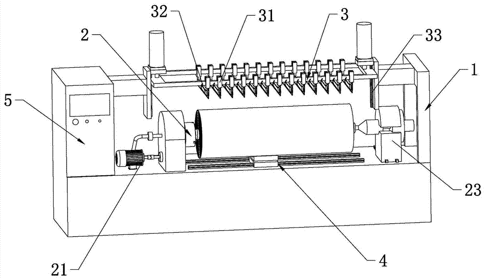
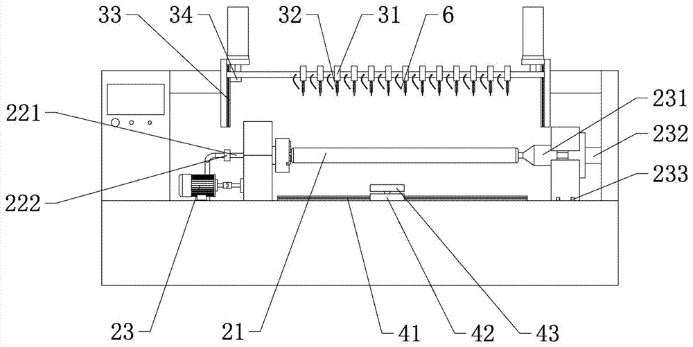
[0029] according to Figure 1 ~ Figure 3 As shown, a floor mat cutting machine includes: a frame 1, a rotating device 2 for driving materials, a cutting table 3 for cutting materials, a feeding device 4 for upper and lower materials, and coordinated control of the operation of each device The control mechanism 5; the rotating device 2 includes a driver 21 fixed on the frame 1, a rotating shaft 22 connected to the driver 21 and a positioning mechanism 23 for supporting and positioning the rotating shaft 22; the cutting table 3 is provided with a plurality of cutting parts Fixed frame 31, cutting piece fixed frame 31 is provided with strip blade 32, and cutting piece fixed frame 31 and blade 32 joints are also provided with tension adjustment mechanism, thereby ensure the degree of tension of blade 32, cutting piece fixed frame 31 Adjustable connection with the cutting table 3, so that the distance between the blades 32 can be adjusted, a sliding mechanism 33 is provided between...
Embodiment 2
[0035] The difference from the above-mentioned embodiment 1 is that, according to Figure 4 As shown, the size of each cutting unit 323 is different, and the cutting unit 323 located in the middle section of the blade area 321 is smaller in size than the cutting units 323 on both sides of the blade area 321 and arranged more closely. For roll-shaped materials, under the same amount of feed, the blade area facing the center of the circle will bear more cutting volume. By setting up a tighter cutting unit 323 in the middle section of the blade area 321, the cutting efficiency can be effectively improved, and Extend tool life.
Embodiment 3
[0037] The difference from the above-mentioned embodiment 1 is that, according to figure 2 As shown, the cutting table 3 is provided with a distance sensor 34 for controlling the stroke of the cutting table 3 to further control the movement range of the cutting table 3 so as to ensure the cutting amount.
PUM
 Abstract
Description
Claims
Application Information
 - R&D
- Intellectual Property
- Life Sciences
- Materials
- Tech Scout
- Unparalleled Data Quality
- Higher Quality Content
- 60% Fewer Hallucinations
Browse by: Latest US Patents, China's latest patents, Technical Efficacy Thesaurus, Application Domain, Technology Topic, Popular Technical Reports.
© 2025 PatSnap. All rights reserved.Legal|Privacy policy|Modern Slavery Act Transparency Statement|Sitemap|About US| Contact US: help@patsnap.com


