Automatic air exhaust device and method for packaging bags

A technology for automatic exhaust and packaging bags, applied in packaging and other directions, can solve the problems of increasing the risk of packaging bag damage, hidden dangers in medical safety, and volume expansion of packaging bags, so as to improve the efficiency of exhaust operation, ensure exhaust quality, and improve the structure of the device. simple effect

Inactive Publication Date: 2016-06-22
SICHUAN NIGALE BIOTECH
View PDF9 Cites 5 Cited by
  • Summary
  • Abstract
  • Description
  • Claims
  • Application Information

AI Technical Summary

Problems solved by technology

[0002] During the production or use of the packaging bag, if there is too much residual air in the packaging bag, the volume of the packaging bag will expand, which will bring inconvenience to the continuous production and packing operation of the packaging bag, and also increase the risk of damage to the packaging bag
Especially in the production process of medical device products, if the packaging bags used for packaging medical devices are damaged by inflation, it will cause pollution of the medical device products inside, which will lead to the existence of medical safety hazards
For example, in the production of large infusion medicines, the pillow packaging machine is a packaging machine for large infusions, which has the advantages of low cost and fast packaging speed. Therefore, it is easy to cause abnormal conditions such as box expansion and damage to the packaging bag when the packaged product is packed, and it is impossible to pack the specified quantity into the carton of the original design size, or the packaging is caused by forced loading. The bag is seriously damaged, resulting in hidden dangers to the quality and safety of product packaging
If the packaging bag is manually vented, not only the efficiency of the venting operation is low, but also the labor cost is increased. In addition, the quality of the venting of the packaging bag cannot be guaranteed to be consistent.

Method used


Image

  • Automatic air exhaust device and method for packaging bags
  • Automatic air exhaust device and method for packaging bags
  • Automatic air exhaust device and method for packaging bags

Examples


Embodiment approach 1

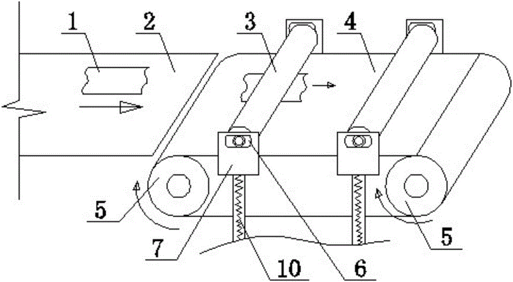
[0022] Such as figure 1 The shown packaging bag automatic exhaust device mainly includes an exhaust drum 3, a belt 4 and a bracket 7, and the bracket 7 is fixedly installed on opposite sides of the belt 4, and guide grooves 6 are set on the bracket 7, and the belt 4 passes through The pulley 5 is supported and moves synchronously with the rotation of the pulley 5. The guide groove 6 is a straight guide groove and is arranged parallel to the belt 4; 6 cooperates and straddles on the belt 4.

[0023] When using the above-mentioned device to perform exhaust treatment on the packaging bag 1 to be exhausted, a motor or other power device can be used to drive the pulley 5 to rotate, so that the belt 4 can move synchronously with the rotation of the pulley 5, and can pass through the conveyor belt. 2. Continuously put the packaging bag 1 into the belt 4. The packaging bag 1 on the horizontal plane of the belt 4 passes under the exhaust roller 3 sequentially with the movement of the...

Embodiment approach 2

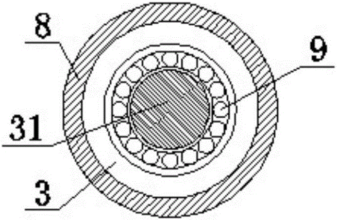
[0026] Such as figure 1 As shown, a tension spring 10 is connected to the exhaust cylinder 3, and one end of the tension spring 10 is flexibly connected to the cylinder shaft 31, so that the tension spring 10 will not be wound on the cylinder shaft 31 as the cylinder shaft 31 rotates. The other end of the extension spring 10 can be fixed on the bracket 7, or can be fixed on other fixed fixtures. For example, when the device and the packaging machine form an assembly line, the other end of the extension spring 10 can be fixed according to the site conditions. fixed on the packaging machine. Others are the same as Embodiment 1.

[0027] The movement elasticity and stability of the exhaust roller 3 can be increased by setting the tension spring 10, so that the contact between the exhaust roller 3 and the packaging bag 1 is good, and the rolling pressure of the exhaust roller 3 on the packaging bag 1 is guaranteed to be more stable and uniform. Thereby, it is beneficial to impro...

Embodiment approach 3

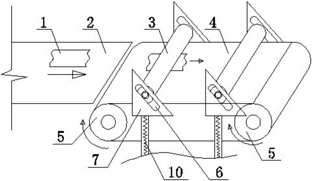
[0029] Such as image 3 As shown, the guide groove 6 is a straight guide groove and is arranged obliquely relative to the belt 4 . Others are the same as Embodiment 1.

[0030] When the packaging bag 1 on the horizontal plane of the belt 4 passes under the exhaust roller 3 sequentially with the movement of the belt 4, due to a certain friction force between the packaging bag 1 and the exhaust roller 3, the exhaust roller 3 While rotating relative to the packaging bag 1, there is also a movement trend of climbing along the guide groove 6 relative to the packaging bag 1. However, since the guide groove 6 is arranged obliquely relative to the belt 4, the exhaust drum 3 can move on its own. Under the action of gravity, the exhaust roller 3 is prevented from climbing up along the guide groove 6 relative to the packaging bag 1, so as to ensure that the exhaust roller 3 always rolls the packaging bag 1, so that the gas in the packaging bag 1 can be automatically and completely exhau...


PUM


Abstract

The invention provides an automatic air exhaust device and method for packaging bags. The automatic air exhaust device of the packaging bags comprises air exhaust rollers (3), a belt (4) and supports (7), wherein the supports (7) are fixedly mounted on the two opposite sides of the belt (4) and provided with guide slots (6); the belt (4) is supported by belt wheels (5) and moves synchronously along with rotation of the belt wheels (5); the air exhaust rollers (3) are arranged on the belt (4) in a stretching across mode through cooperation between roller shafts (31) and the guide slots (6); and while the packaging bags (1) on the belt (4) move along with the belt (4) and pass the portions below the air exhaust rollers (3), the air exhaust rollers (3) exhaust air in the packaging bags (1) by rolling the packaging bags (1). As the air exhaust rollers roll the packaging bags to exhaust air, the air exhaust quality of the packaging bags is improved; and the automatic air exhaust device and method are particularly suitable for the assembly line work of a packaging machine, and have the outstanding advantages of the simple structure, convenient operations and the like.

Description

technical field [0001] The invention relates to the technical field of packaging bag exhaust, in particular to an automatic packaging bag exhaust device and method. Background technique [0002] During the production or use of the packaging bag, if there is too much residual air in the packaging bag, the volume of the packaging bag will expand, which will bring inconvenience to the continuous production and packing operation of the packaging bag, and also increase the risk of damage to the packaging bag. Especially in the production process of medical device products, if the packaging bags used for packaging medical devices are damaged due to inflation, the medical device products inside will be polluted, which will lead to the existence of medical safety hazards. For example, in the production of large infusion medicines, the pillow packaging machine is a packaging machine for large infusions, which has the advantages of low cost and fast packaging speed. Therefore, it is ...

Claims


Application Information

Patent Timeline
IPC IPC(8): B65B61/00
CPCB65B61/00
Inventor 卿建华
Owner SICHUAN NIGALE BIOTECH
Why Eureka
Try Eureka