Escape device of bentonite improving shield tunneling machine and construction method thereof

A construction method and technology of shield machine, which are used in earth-moving drilling, mining equipment, tunnels, etc., can solve the problems of increased binding force of the cutter head, complicated geological conditions, and the inability of the cutter head to rotate, so as to reduce the binding force and reduce the binding force of the cutter head. Good economic benefits and short construction period

Inactive Publication Date: 2016-06-22
CHINA RAILWAY TUNNEL
View PDF7 Cites 14 Cited by
  • Summary
  • Abstract
  • Description
  • Claims
  • Application Information

AI Technical Summary

Problems solved by technology

[0002] At the beginning of this century, shield tunnel construction has been widely used in my country. However, due to the complex geological conditions in various regions of our country, shield tunneling often occurs during shield construction.
In particular, when the shield machine is excavating in the dense sand layer, the muck around the cutter head and in the soil bin gradually loses water and deposits and consolidates around the cutter head due to long-term shutdown. The amount of deposition gradually increases with time, and the sand The porosity of the strata gradually decreases, and the binding force of the formation to the cutterhead gradually increases, causing the muck to lock the cutterhead, and the starting torque is greater than the rated torque, resulting in the cutterhead being unable to rotate
The traditional methods to solve this kind of shield tunneling include opening the cabin in the hole, digging shafts after slotting on the ground, etc. However, these methods have a long construction period and high safety risks

Method used


Image

  • Escape device of bentonite improving shield tunneling machine and construction method thereof
  • Escape device of bentonite improving shield tunneling machine and construction method thereof
  • Escape device of bentonite improving shield tunneling machine and construction method thereof

Examples


Embodiment Construction

[0030] The technical solutions in the embodiments of the present invention will be clearly and completely described below in conjunction with the accompanying drawings in the present invention. Apparently, the described embodiments are only illustrative partial implementations of the present invention, and are not intended to limit the scope of the present invention. , any equivalent changes and modifications made by those skilled in the art without departing from the concepts and principles of the present invention shall fall within the protection scope of the present invention.

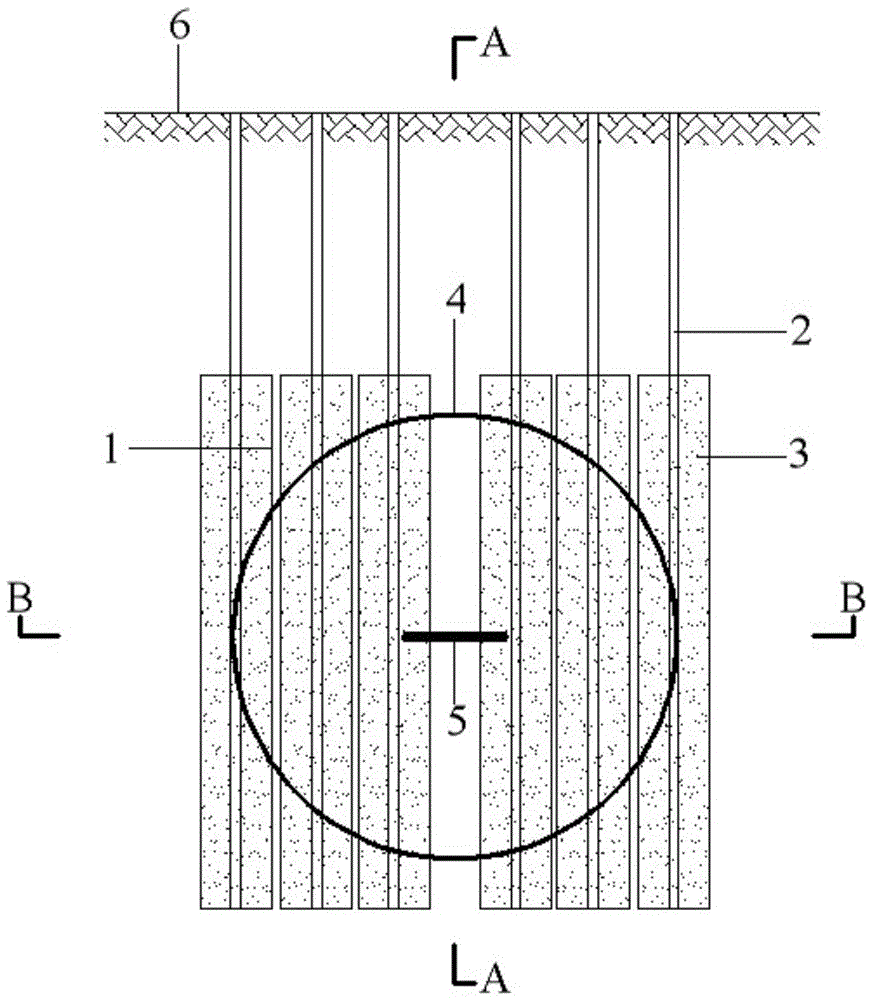
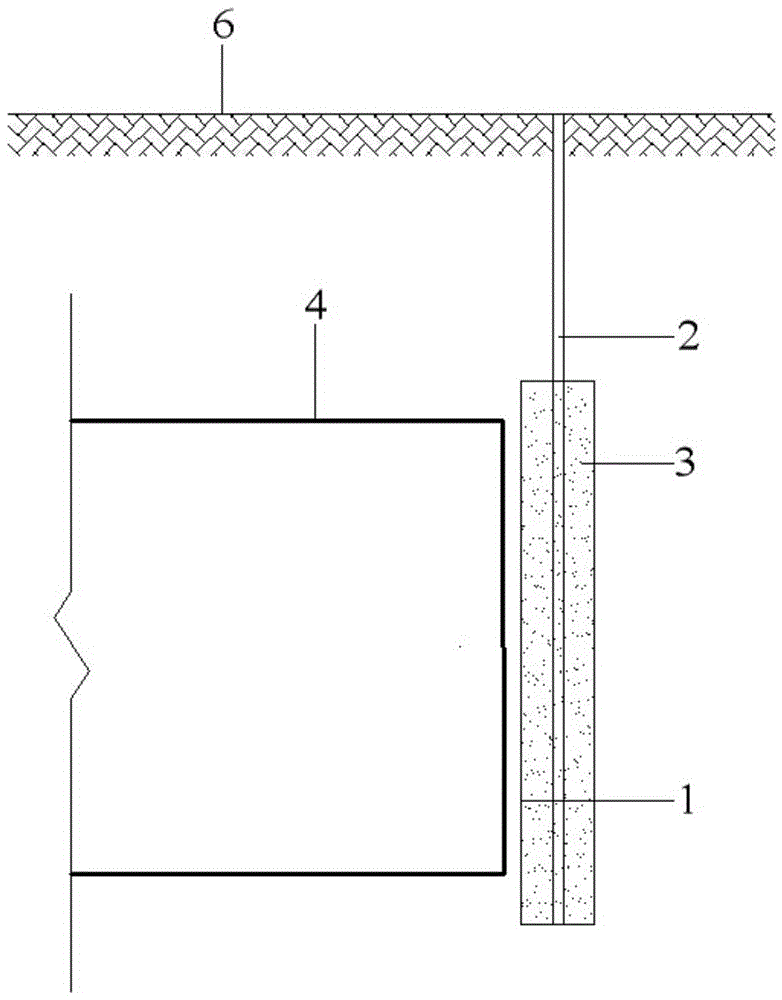
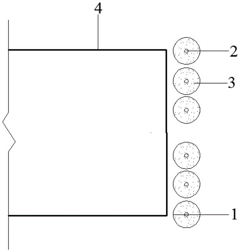
[0031] refer to Figure 1-3 As shown in the figure, a bentonite-improved soil shield machine relief device of the present invention includes a plurality of rotary spray piles 1 located in front of the cutter head of the shield machine 4 and arranged left and right along the cross section of the cutter head.

[0032] Specifically, in the aforementioned bentonite-improved soil shield machine trapping ...


PUM


Abstract

The invention belongs to the technical field of shield tunnel construction, particularly relates to an escape device of a bentonite improving shield tunneling machine and a construction method. The escape device comprises an even number of jet grouting piles, wherein the jet grouting piles are three-pipe jet grouting piles, the pile forming diameter is 800-1000 mm, the specific number of the jet grouting piles is determined according to soil layer parameters and the cutterhead diameter of the shield tunneling machine, the jet grouting piles are located at the positions 400-500 mm away from the front of a cutterhead of the shield tunneling machine, jet grouting pile slurry is specially-prepared bentonite slurry, the mass ratio of bentonite to water to CMC to soda ash is 200 to 900 to 1 to 2, and the stratum which the structures of the jet grouting piles are applicable to is a dense sand layer. The construction method comprises the three steps: first step, the positions of the jet grouting piles are arranged; second step, the jet grouting pile slurry is prepared; third step, the bentonite slurry is rotary jet grouting for pile forming. The construction steps are simple, the escape problem of the shield tunneling machine in the dense sand layer can be effectively and quickly solved, a construction period is short, the construction cost is low, and good economic benefits are obtained.

Description

technical field [0001] The invention belongs to the technical field of shield tunnel construction, and in particular relates to a bentonite-improved soil body shield machine relief device and a construction method thereof, and is especially suitable for tunnel construction of a shield machine in a dense sand layer. Background technique [0002] At the beginning of this century, the construction of shield tunnels has been widely used in my country. However, due to the complex geological conditions in various regions of our country, the shield machine is often trapped during shield construction. In particular, when the shield machine is excavating in the dense sand layer, the muck around the cutter head and in the soil bin gradually loses water and deposits and consolidates around the cutter head due to long-term shutdown. The amount of deposition gradually increases with time, and the sand The porosity of the strata gradually decreases, and the binding force of the formation ...

Claims


Application Information

Patent Timeline
Patent Type & Authority Applications(China)
IPC IPC(8): E21D9/08E21D9/00
CPCE21D9/08E21D9/002
Inventor 刘凯鄢春艳叶康慨王玉祥李达齐彬王虬鹏和学庆侯世杰和伟
Owner CHINA RAILWAY TUNNEL
Why Eureka
Try Eureka