Energy recovery control system and lifting equipment

A technology of energy recovery and control system, which is applied in the direction of mechanical equipment, fluid pressure actuation system testing, fluid pressure actuation system components, etc., and can solve the problem that the falling speed of heavy objects cannot be controlled

Active Publication Date: 2016-06-22
XUZHOU HEAVY MASCH CO LTD
View PDF7 Cites 5 Cited by
  • Summary
  • Abstract
  • Description
  • Claims
  • Application Information

AI Technical Summary

Problems solved by technology

Furthermore, it also solves the problem that th...

Method used


Image

  • Energy recovery control system and lifting equipment
  • Energy recovery control system and lifting equipment
  • Energy recovery control system and lifting equipment

Examples


Embodiment Construction

[0030]The following will clearly and completely describe the technical solutions in the embodiments of the present invention with reference to the accompanying drawings in the embodiments of the present invention. Obviously, the described embodiments are only some, not all, embodiments of the present invention. The following description of at least one exemplary embodiment is merely illustrative in nature and in no way taken as limiting the invention, its application or uses. Based on the embodiments of the present invention, all other embodiments obtained by persons of ordinary skill in the art without creative efforts fall within the protection scope of the present invention.

[0031] The relative arrangements of components and steps, numerical expressions and numerical values ​​set forth in these embodiments do not limit the scope of the present invention unless specifically stated otherwise.

[0032] At the same time, it should be understood that, for the convenience of de...


PUM


Abstract

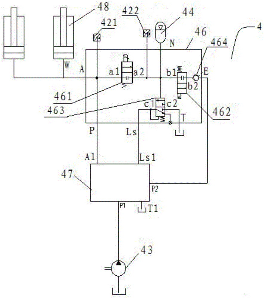
The invention discloses an energy recovery control system and lifting equipment. The energy recovery control system comprises a hydraulic pump, a main valve, a hydraulic execution element, an energy accumulator, a first control valve and a second control valve; the main valve has a first main valve pressure oil port, a second main valve pressure oil port, a main valve working oil port and a main valve oil discharge port; the hydraulic execution element has an execution element working oil port; an outlet of the hydraulic pump is connected with the first main valve pressure oil port; the main valve working oil port is connected with the execution element working oil port; the execution element working oil port is connected with the energy accumulator through the first control valve; the first control valve controls the connection and the disconnection of the actuation element working oil port and the energy accumulator; the energy accumulator and the second main valve pressure oil port are connected through the second control valve; and the second control valve controls the connection and the disconnection of the energy accumulator and the second main valve pressure oil port. The energy recovery control system can directly act the energy, absorbed by the energy accumulator, on the main valve when being applied to the lifting equipment, and is wider in application range.

Description

technical field [0001] The invention relates to the field of engineering machinery, in particular to an energy recovery control system and lifting equipment. Background technique [0002] Forklifts are widely used in workshops, warehouses and other occasions that require high environmental conditions. Its structure and working characteristics determine that when the fork lifts heavy objects up, it needs a lifting cylinder to provide driving force, that is, the hydraulic cylinder provides energy. The hydraulic energy is converted into gravitational potential energy; and when the fork lifts the heavy object and descends, its potential energy is released. This potential energy is very considerable compared to a forklift that works frequently. If it cannot be used effectively, it will not only cause energy waste, but also cause an increase in the temperature of the hydraulic oil, which will affect the performance of the system. Therefore, it is necessary to design an energy sto...

Claims


Application Information

Patent Timeline
IPC IPC(8): F15B1/02F15B19/00F15B21/14B66F9/22
CPCB66F9/22F15B1/02F15B19/005F15B21/14
Inventor 叶海翔张付义刘威张震孙飞
Owner XUZHOU HEAVY MASCH CO LTD
Why Eureka
Try Eureka