Equivalent leakage current error influence test device and test method thereof

A test device and leakage current technology, which is applied in the direction of measuring devices, measuring electrical variables, instruments, etc., can solve problems such as difficulty in on-site verification, poor response characteristics of transformers, difficulty in satisfying fast and accurate action of relay protection, etc., and achieve a reduction in test Difficulty, operability improvement effect

Active Publication Date: 2016-06-22
STATE GRID CORP OF CHINA +1
View PDF3 Cites 8 Cited by
  • Summary
  • Abstract
  • Description
  • Claims
  • Application Information

AI Technical Summary

Problems solved by technology

Electric field simulation shows that for a 1000kV CVT, the capacitive current flowing from the high-voltage arm of the voltage divider into the ground can reach 20mA, causing significant measurement errors
Measures are usually taken to increase the main capacitance of the voltage divider to reduce the influence of stray currents, but even if the capacitance is increased to 10000pf, the accuracy level of UHV CVT is still difficult to reach the 0.1 standard
[0006] 2) On-site verification is difficult:
The introduction of energy storage components makes the response characteristics of transformers worse, and it is difficult to meet the requirements of fast and accurate action of UHV power grid relay protection
At present, there is no test method for the influence of equivalent leakage current error on capacitive voltage transformers. This test method is the first case

Method used


Image

  • Equivalent leakage current error influence test device and test method thereof
  • Equivalent leakage current error influence test device and test method thereof
  • Equivalent leakage current error influence test device and test method thereof

Examples


Embodiment Construction

[0034] The specific implementation manners of the present invention will be further described in detail below in conjunction with the accompanying drawings.

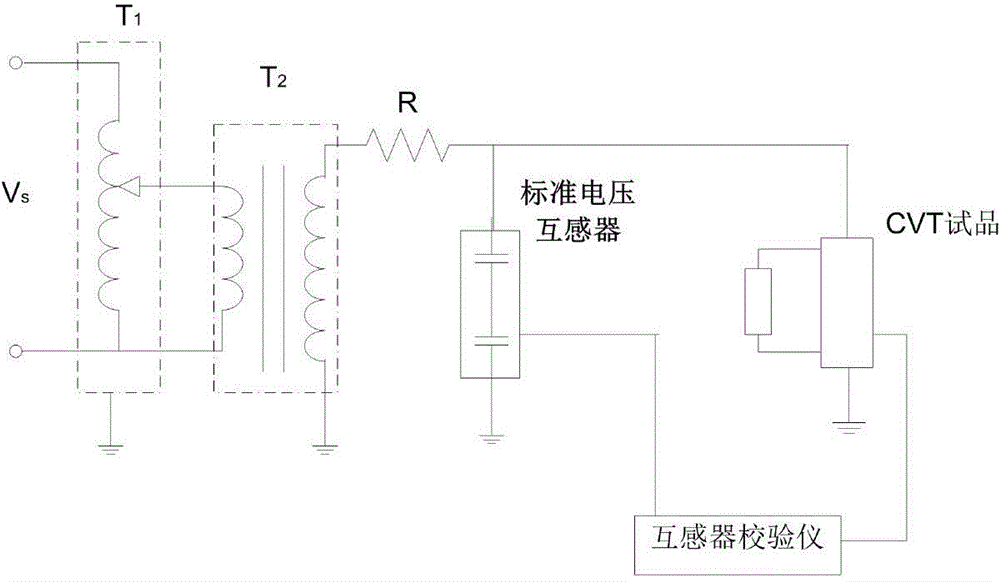
[0035] The invention provides an equivalent leakage current error influence test device, which includes a voltage regulator T 1 , test transformer, standard transformer, equipotential shielding capacitive voltage transformer sample and resistor body; the power supply voltage passes through the test transformer T 2 and the current-limiting resistor are connected to the primary side of the standard capacitive voltage transformer and the equipotential shielding capacitive voltage transformer; the test transformer T 2 primary side of the regulator with T 1 One end of the secondary side is grounded, and the other end is connected to one end of the current limiting resistor R; the other end of the current limiting resistor R is respectively connected to the primary side of the standard voltage transformer and the primary side...


PUM


Abstract

The invention relates to an equivalent leakage current error influence test device and a test method thereof. The device includes a voltage regulator, a test transformer, a standard transformer, a CVT test piece and a resistance body; power source voltage is connected into the primary sides of the standard voltage transformer and the CVT test piece through the test transformer and a current limiting resistor; the primary side of the test transformer is connected with the voltage regulator; one end of the secondary side of the test transformer is grounded, and the other end of the secondary side of the test transformer is connected with one end of the current limiting resistor; the other end of the current limiting resistor is connected with the primary side of the standard voltage transformer and the primary side of the CVT test piece; the secondary side of the standard voltage transformer and the secondary side of the CVT test piece are both connected with a transformer calibrator; and the resistance body is connected in parallel with two ends of a single capacitor unit of the CVT test piece so as to simulate equivalent leakage current. With the equivalent leakage current error influence test device and the test method thereof of the invention adopted, the leakage current situation of the CVT due to rain and dust is successfully simulated, and it is verified that the accuracy of the CVT can still satisfy a requirement for a high accuracy grade under the leakage current situation.

Description

technical field [0001] The invention relates to a power system transformer device and a method thereof, in particular to an equivalent leakage current error influence test device and a test method thereof. Background technique [0002] With the engineering application of UHV (AC 1000kV and above) transmission technology, the accurate measurement of UHV grid voltage has become a key technical problem to be studied and solved. The power frequency high voltage measurement devices widely used in the power system mainly include electromagnetic voltage transformers and capacitive voltage transformers (both of which are passive voltage measurement systems), which can basically meet the requirements of 500kV and below voltage level voltage measurement and Requirements for relay protection. Photoelectric voltage transformers and electronic voltage transformers (both of which are active voltage measurement systems) are still in the process of research and development and trial operat...

Claims


Application Information

Patent Timeline
Patent Type & Authority Applications(China)
IPC IPC(8): G01R35/02
Inventor 董巍李志麒查鲲鹏
Owner STATE GRID CORP OF CHINA
Why Eureka
Try Eureka