
A temperature control circuit and method for hot knife mechanism

A technology of temperature control circuit and hot knife, applied in temperature control, non-electric variable control, control/regulation system, etc., can solve the problem of calculating the blade temperature from the resistance value of the hot wire blade, not monitoring the temperature, and increasing the power of the hot rod And other issues

Inactive Publication Date: 2017-11-21
SHENYANG INST OF AUTOMATION - CHINESE ACAD OF SCI
View PDF3 Cites 0 Cited by
  • Summary
  • Abstract
  • Description
  • Claims
  • Application Information

AI Technical Summary

Problems solved by technology

At present, existing hot knife mechanisms, such as "CN201320642944.X Hot Cutting Knife" and "CN201020158354.6 A Locking and Separating Device Driven by Hot Knife", do not have the function of monitoring temperature. The power of the hot rod must be increased, resulting in energy loss
In addition, the blades of existing hot knives are mostly made of copper or copper alloys, for example, "CN201110049274.6 Hot Knife for Wax Figure Engraving Machine with Quickly Replaceable Knife Head", its resistance has little relationship with temperature change, and the resistance of the hot wire blade cannot be used. The temperature of the blade is calculated from the value, so it is necessary to add an additional temperature sensor to achieve the effect of temperature feedback and increase the production cost

Method used


Image

  • A temperature control circuit and method for hot knife mechanism
  • A temperature control circuit and method for hot knife mechanism
  • A temperature control circuit and method for hot knife mechanism

Examples


Embodiment Construction

[0022] The present invention will be further described in detail below in conjunction with the accompanying drawings and implementation examples.

[0023] like figure 1 As shown, the whole system is composed of power supply, control circuit and blade body. like Figure 4 As shown, the blade body is mainly composed of an end cover 1, a spring 2, a blade body 3, a slider 4, a connecting rod 5, a set screw 6, an electrode 7 and an electric heating element 8. Wherein, end cover 1 is connected with the left end of spring 2; The right end of spring 2 is connected with the left end of slide block 4; Slide block 4 is positioned at the cavity of knife body 3; The connection with the left end of the electrode 7 adopts a direct plug-in type, and then is fixed with a set screw and connected with the relative thread. The right end of the electrode 7 is connected with the heating element 8 .

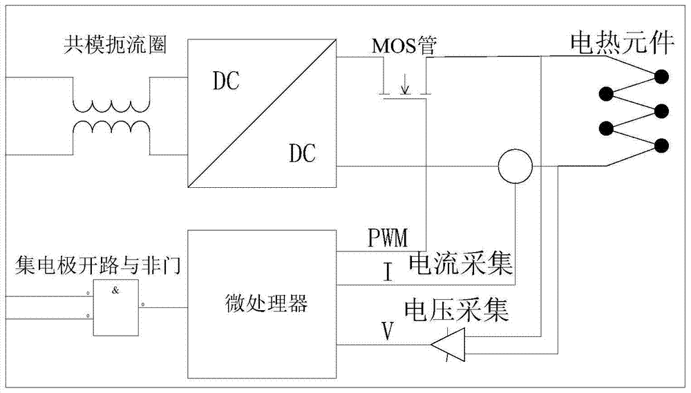
[0024] The temperature control circuit of the hot knife is as figure 2 shown. The temperatu...


PUM


Abstract

The invention relates to a temperature control circuit for a hot knife mechanism, including a common mode choke coil, a DC / DC power supply module, a MOS tube, an MCU, a voltage and current acquisition circuit, an open collector NAND gate and an electric heating element; The input terminal of the common mode choke coil is used to connect to the BUS bus of the external power supply, and the output terminal is connected to the input terminal of the DC / DC power supply module; the positive output terminal of the DC / DC power supply module is connected to the drain of the MOS tube; the MOS tube The gate is connected to the MCU, and an electric heating element is connected between the source and the negative output terminal of the DC / DC power supply module; the negative output terminal of the DC / DC power supply module is connected to the MCU through a voltage and current acquisition circuit; the MCU It is connected with the host computer through the open collector NAND gate. The method is to realize the temperature control of the electric heating element through a closed-loop control algorithm according to the linear proportional relationship between the resistance value and the temperature. The hot wire blade of the present invention works in a constant power mode, and by adjusting the voltage and current of the hot wire blade, the resistance of the hot wire blade is controlled, so as to achieve the purpose of controlling the temperature of the hot wire blade.

Description

technical field [0001] The invention relates to a temperature control circuit with temperature control and state monitoring functions and a temperature control method thereof, which can be applied to temperature control of various hot knife mechanisms. Background technique [0002] The hot knife is a knife used to cut objects after heating. Its main purpose is: cutting cable insulation layer, scraping off other objects that need high temperature to be scraped off, cutting braid, etc. At present, existing hot knife mechanisms, such as "CN201320642944.X Hot Cutting Knife" and "CN201020158354.6 A Locking and Separating Device Driven by Hot Knife", do not have the function of monitoring temperature. The use power of the hot rod must be increased, resulting in energy loss. In addition, the blades of existing hot knives mostly use copper or copper alloys. For example, "CN201110049274.6 Hot Knife for Wax Figure Engraving Machines Can Quickly Replace the Knife Head". The temperatu...

Claims


Application Information

Patent Timeline
Patent Type & Authority Patents(China)
IPC IPC(8): G05D23/24
Inventor 阳方平张涛李涛杨君娟袁顺宁张峰崔龙李洪谊
Owner SHENYANG INST OF AUTOMATION - CHINESE ACAD OF SCI
Learn More