Shift register unit, grid driving circuit and driving method thereof

A gate drive circuit, shift register technology, applied in static memory, digital memory information, instruments, etc., can solve the problems of inability to guarantee pixel charging and long reset time of gate drive signal, so as to reduce leakage and ensure charging. time, the effect of stable working conditions

Active Publication Date: 2016-06-22
BOE TECH GRP CO LTD
View PDF17 Cites 50 Cited by
  • Summary
  • Abstract
  • Description
  • Claims
  • Application Information

AI Technical Summary

Problems solved by technology

[0004] The purpose of the present invention is to provide a shift register unit, a gate drive circuit and a drive method thereof, which are used to solve the problem that the pixel cannot be well charged due to the long reset time of the gate drive signal

Method used


Image

  • Shift register unit, grid driving circuit and driving method thereof
  • Shift register unit, grid driving circuit and driving method thereof
  • Shift register unit, grid driving circuit and driving method thereof

Examples


Embodiment Construction

[0044] In order to further illustrate the shift register unit, the gate driving circuit and the driving method thereof provided by the embodiments of the present invention, a detailed description will be given below in conjunction with the accompanying drawings.

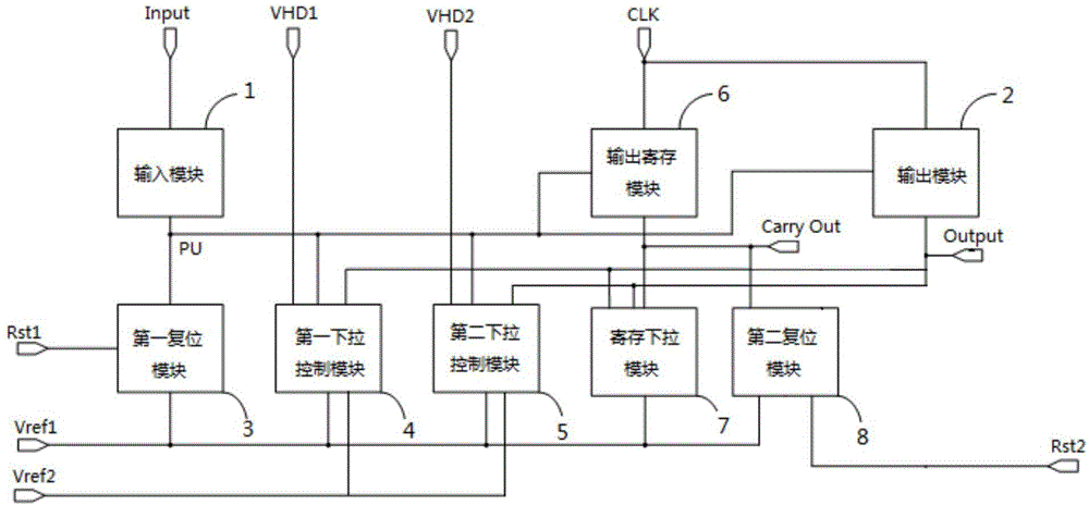
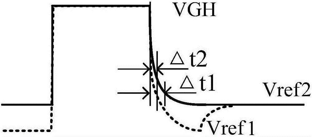
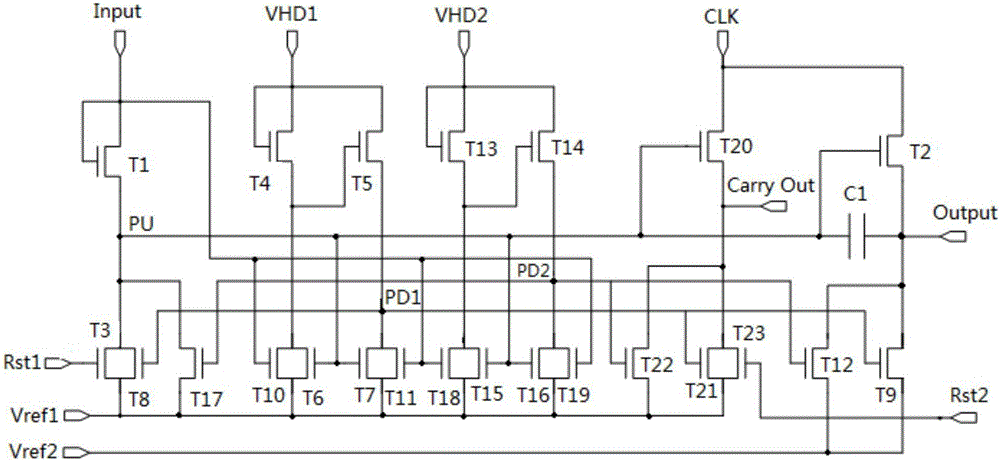
[0045] see figure 1 and Figure 4, a working cycle of the shift register unit provided by the embodiment of the present invention includes: input phase t1, output phase t2, reset phase t3 and holding phase t4, the shift register unit includes: input module 1, output module 2, first reset Module 3 and the first pull-down control module 4. The input module 1 is in the input stage t1, used to pull up the voltage of the pull-up node PU under the action of the input signal Input; the output module 2 is used in the output stage t2, used to output the module 2 under the action of the clock signal CLK The output terminal of the output terminal outputs the gate drive signal Output, and further pushes up the voltage of the p...


PUM


Abstract

The invention discloses a shift register unit, a grid driving circuit and a driving method thereof, relates to the technical field of display, and solves the problems that great charging of pixels cannot be guaranteed due to long reset time of a grid driving signal. According to the shift register unit, an input module is used for pulling up voltage of a pull-up node under the effect of an input signal in the input phase; an output module is used for outputting the grid driving signal under the effect of a clock signal and further pushing up voltage of the pull-up node in the output phase; the output module is used for pulling down voltage of the output end of the output module to reference voltage under the effect of the clock signal in the reset phase; and a first pull-down control module is used for regulating voltage of the output end of the output module to grid turn-off voltage from reference voltage under the effect of a first pull-down control signal. The shift register unit is used for providing the grid driving signal.

Description

technical field [0001] The invention relates to the field of display technology, in particular to a shift register unit, a gate drive circuit and a drive method thereof. Background technique [0002] With the continuous development of display technology, more and more display devices adopt the Gate On Array (GOA) technology, which directly integrates the gate drive circuit on the non-display area of ​​the array substrate. The frame width of the array substrate is greatly reduced. The gate drive circuit integrated on the array substrate includes several shift register units, each shift register unit corresponds to a gate line on the array substrate, and drives the gate line by outputting a gate drive signal, And the gate driving signal will be reset to the gate off voltage after completing the driving of the gate line, so that the follow-up work can be performed normally. [0003] However, since the time allocated to each row of pixels in the display device is fixed, and wi...

Claims


Application Information

Patent Timeline
Patent Type & Authority Applications(China)
IPC IPC(8): G09G3/20G11C19/28
CPCG09G3/20G09G3/3266G09G3/3677G09G2300/0408G09G2310/0267G09G2310/0286G11C19/28G11C19/287
Inventor 商广良姚星韩承佑高玉杰张元波陈明田正牧董学
Owner BOE TECH GRP CO LTD
Why Eureka
Try Eureka